
Page 419 - Maxwell House
P. 419
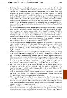
MORE COMPLICATED ELEMENTS OF FEED LINES                                 399


            1.  Following the even-  and odd-mode  principle,  we can  represent   = 1 = 05 + 0.5
                                                                         1
               and  = 0 = 0.5 + (−0.5) and consider two excitation cases illustrated in Figure 8.2.8c.
                    3
            2.  The first case corresponds to port1 and port3 being excited equally and in phase. Such
               even-mode as the whole structure cannot exist behind WRs and propagate over WR of
               double  width. To verify this consider the distribution of  a  longitudinal  component of
               magnetic field. If so, this even-mode should transfer itself into one or multiple modes of
               double width WR. Therefore, the break in metal wall plays the role of a discontinuity
               creating the reflecting waves in port1 and port3. The matching rod shown in Figure 8.2.8b
               creates the other reflected waves. Evidently, they go back to these ports and could diminish
               the mismatch and improve the isolation simultaneously. Remind that in a forward hybrid
               port3 must be isolated.
            3.  We can interpret the transformation of the even-mode as the process of radiation EM waves
               from port1 and port3 into the double width WR. Due to the full symmetry, the central
               radiation peak of such aperture antenna must be in the plane of symmetry. If so, all the
               excited TE-modes must have  E-field maximum  in  this plane, i.e. carry the odd first
               subscript like TE10, TE30, and so on. Looking back at the expression (6.21) in Chapter 6,
               we see that TE30-mode propagation can be prevented if  < 2 < 3/2 that we are going
               to assume. According to (6.21) the propagation constant   of remaining TE10-mode in
                                                               10
                                                                    2
                                                                ⁄
               the WR of double width, i.e. 2, is equal to  10  = �1 − ( 4) .
            4.  The situation with the odd-mode excitation is much easier. Looking back at Figure 8.2.8c,
               we see that this mode has the E-field structure of TE20-mode. Therefore, it follows to the
               WR of double width without any transformation and reflection. According to (6.21) the
               propagation constant     of TE20-mode in the WR of double  width is equal to  20  =
                                  20
               �1 − ( 2) .
                            2
                       ⁄
            5.  Both modes propagate over the slot getting the different phase shift   and  . Here L
                                                                       10
                                                                              20
               is the slot length. Reaching the end of slot, the double width WR TE10-mode breaks up into
               two TE10-modes of equal magnitude and phase following to port2 and port4. Meanwhile,
               TE20-mode breaks up too into two TE10-modes of equal magnitude following to port2 and
               port4, but it induces these ports in opposite phase. Therefore, the total magnitude in port3
               is   = 0.5( − 10   +   − 20  ) =   −  cos[( 10  −  )/2]  while in port4 is  =
                   3
                                                                                    4
                                                           20
               0.5(  − 10   −  − 20  ) = −  −  sin[( 10  −  )/2]. Here  = ( 10  +  )/2.
                                                     20
                                                                            20
            6.  Our final task is design 3-dB hybrid  meaning that it should be  | | = | |
                                                                                3
                                                                                      4
               or cos[( 10  −  )/2] = sin[( 10  −  )/2]  and  thus tan[( 10  −  )/2] = 1.  It
                                               20
                            20
                                                                          20
               turns out that ( 10  −  )/2 = /4 or the equity 2 = /( 10 −  )  defines the slot
                                                                       20
                                  20
               length at some central frequency.
            7.  Working out the equations above, we can evaluate the phase shift between fields in port2
               and port4:  / = − =   −/2  at the same central frequency. Therefore, the short-slot
                         4
                            2
               WR hybrid can be classified as a quadrature 3-dB coupler.
            8.  The reciprocal principle tells us that the same excitation of port2 and port4 in magnitude
               and  (−90°)  phase shift means that the doubled power goes into port1 leaving port3
               isolated. Switch this phase to +90° and all power appears in port3 with port1 isolated.
               Such phase-manipulation technology lets develop electronically controlled and ultrafast
               switches for high and extremely high power.
            9.  The simple CST model was developed based on these equations. The most impressive
               result is shown in Figure 8.2.8d. The plot demonstrates the active part of Poynting’s vector,
               i.e. the direction and density of active power flow at the central frequency. The EM power