
Page 415 - Maxwell House
P. 415
MORE COMPLICATED ELEMENTS OF FEED LINES 395
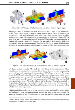
Figure 8.2.5 a) WR magic-T, b) Port1 excitation, c) E-field structure at port4 input
5
Suppose the energy of dominant TE10-mode is injected in port1. Figure 8.2.5b demonstrates
vertical E-field orientation and its intensity at some moment of time. Due to the symmetry, the
energy coming to the port2 and port3 is equal and in phase. Notice that the wave approaching
port4 from port1 is vertically polarized and, thus, oriented along the longitudinal axis of WR in
port4. If so, such wave can excite in this WR mainly TM and other high nonpropagating in
standard WR modes as Figure 8.2.5c illustrates. The magnitude of the penetrating fields drops
exponentially being the evanescent modes. Therefore, port4 is highly isolated (50 dB and more
depending on fabrication accuracy) at all frequencies as long as WR in port4 stays single mode.
Figure 8.2.6 a) Port4 excitation, b) E-field structure at port1, c) Matched magic-T
Let change excitation sending TE10-mode in port4. Figure 8.2.6a demonstrates E-field
orientation and its intensity at some moment of time. Due to the symmetry, the energy coming
to the port2 and port3 is equal but in the opposite or 180° phase (red arrows). The unique
feature of a WR T-magic is that this out-of-phase shift is frequency independent. Notice that the
wave approaching port1 from port4 is horizontally polarized and, thus, oriented in parallel to
WR broad wall in port1. If so, such wave can excite in this WR mainly TEon and other high
nonpropagating in standard WR modes as Figure 8.2.6b illustrates. Clearly, the magnitude of
the penetrating fields drops exponentially being the evanescent modes. Therefore, port1 is
highly isolated (50 dB and more depending on fabrication accuracy) at all frequencies as long
as WR in port1 stays single mode.
Evidently and with accordance to reciprocal principle, the energy of two TE10 waves exciting
port2 and port3 in phase and equal magnitude proceeds into port1 keeping port4 isolated. The
same way, the energy of two TE10 waves exciting port2 and port3 in opposite phase and equal
5 Public Domain Image, source: https://www.feko.info/applications/white-papers/waveguide-magic-
tee/modelling-of-a-magic-t-waveguide-coupler