
Page 411 - Maxwell House
P. 411
MORE COMPLICATED ELEMENTS OF FEED LINES 391
8.2.3 Continuous Directional Coupler
A standard edge-coupled microstrip version of the continuous directional coupler is depicted in
2
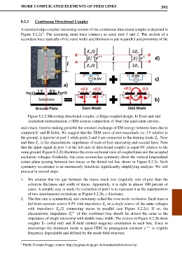
Figure 8.2.2a . The assuming main trace connects as usual port 1 and 2. The section of a
secondary trace typically of the same width and thickness is put in parallel and proximity of the
Figure 8.2.2 Microstrip directional coupler: a) Edge-coupled design, b) Even and odd
excitation representation, c) EM sources connection, d) Step line equivalent circuits.
main trace, thereby making possible the constant exchange of EM energy between lines due to
common E- and H-fields. We suggest that the TEM wave of unit magnitude, i.e. 1V relative to
the ground, is injected at port 1 while ports 2 and 4 are connected to the dummy loads . Now
and then is the characteristic impedance of each of four microstrip and coaxial lines. Note
that the input signal in port 3 at the left side of directional coupler is equal 0V relative to the
same ground. Figure 8.2.2b illustrates the cross-sectional view of coupled lines and the accepted
excitation voltages. Evidently, this cross section has symmetry about the vertical longitudinal
center plane passing between two traces as the dotted red line shows in Figure 8.2.2a. Such
symmetry occurrence is an enormously beneficial significantly simplifying analysis. We will
proceed in several steps.
1. We assume that the gap between the traces much less (regularly tens of µm) than the
substrate thickness and width of traces. Apparently, it is right in almost 100 percent of
cases. A suitable way to study the excitation of port1 is to represent it as the superposition
of two simultaneous excitations as Figure 8.2.2b, c illustrates.
2. The first one is symmetrical, and customary called the even-mode excitation. Each trace is
fed from separate source 0.5V with impedance or a single source of the same voltages
with impedance /2 connecting traces in parallel (see Figure 8.2.2c). If so, the
++ of this combined line should be almost the same as the
characteristic impedance
impedance of single microstrip with double trace width. The vectors in Figure 8.2.2b show
roughly E- (solid red) and H-field (dotted magenta) orientation in such line. Since in
microstrips the dominant mode is quasi-TEM its propagation constant ++ is slightly
frequency dependable and defined by the mode field structure.
2 Public Domain Image, source: http://paginas.fe.up.pt/~hmiranda/etele/microstrip/