
Page 409 - Maxwell House
P. 409
MORE COMPLICATED ELEMENTS OF FEED LINES 389
If a directional coupler is backward, swap the indices as 3 ↔ 4 in (8.4) and following
expressions. Six main parameters usually measured in dB describe the directional coupler
parameters over frequency:
1. Insertion loss (IL) =10 log (1/2) = 20 log (1/| |) ≤ (0.1 − 0.5) dB
10
21
10
2. Return Loss (RL) = 20 log (1/| |) ≥ 20 dB
10
11
3. Coupling factor (C) =10 log (1/3) = 20 log (1/| |) ≥ 20 dB
31
10
10
4. Isolation (I) =10 log (1/4) = 20 log (1/| |). Between (5 – 50) dB depending on
10
10
41
requirements.
5. Directivity (D) = 10 log (4/3) = 20 log (| |/| |) ≥ 20 dB
10
31
41
10
6. Power Division (PD) = 10 log (2/4) = − = 20 log (| |/| |)
10
10
41
21
The presented numerical data are for guidance only. Additional parameters can be power
handling, sizes, weight, thermal stability, the precision of coupling factor, etc. Keep in mind
that the mutual coupling could be discrete or continuous. Nevertheless, the essence of energy
exchange between the lines is practically the same as in linear arrays (discrete or continuous)
with Progressive Phase Distribution we have discussed in Section 5.4.7 of Chapter 5. The
critical difference is that now the antenna in the form of hole radiates from the so-called main
line connecting, for example, port1 and port2 to secondary one between port 3 and 4, not in
surrounding infinite space. Therefore, the radiated field energy stays close to antenna thereby
enabling the energy return to the main line. It means the continuous energy exchange between
two coupled lines in any reciprocal directional coupler. To simplify the following study, we
will neglect this secondary interaction considering relatively weak coupling as soon as the most
propagating energy remains in the main line.
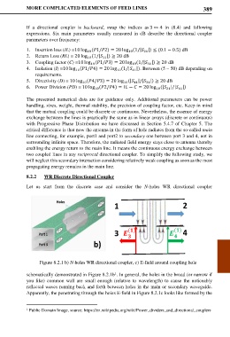
8.2.2 WR Discrete Directional Coupler
Let us start from the discrete case and consider the N-holes WR directional coupler
1 2
3 4
b)
Figure 8.2.1 b) N-holes WR directional coupler, c) E-field around coupling hole
schematically demonstrated in Figure 8.2.1b . In general, the holes in the broad (or narrow if
1
you like) common wall are small enough (relative to wavelength) to cause the noticeably
reflected waves running back and forth between holes in the main or secondary waveguide.
Apparently, the penetrating through the holes E-field in Figure 8.2.1c looks like formed by the
1 Public Domain Image, source: https://en.wikipedia.org/wiki/Power_dividers_and_directional_couplers