
Page 405 - Maxwell House
P. 405
MORE COMPLICATED ELEMENTS OF FEED LINES 385
Introduction
Now we are almost ready to “fight” with more complex problems in microwave frequency range
between 300 MHz and 300 GHz. At these frequencies, the wavelength is often comparable to
the sizes of devices and their elements. It means that EM wave propagation effects become
essential and manifest themselves in the form of radiation, interaction with charged particles in
material atoms and molecules, dispersion, time delay, complicated dependency on frequency
of active and reactive energy stored in EM fields, and many others. We should remember that
all of them could be estimated with vital accuracy through the numerical or analytical solutions
of Maxwell’s equations as well as the measurements. Nevertheless, we will try to keep as much
as possible the traditional and descriptive methodology based on lumped-element circuit theory.
8.1 IN-LINE RESONATORS
8.1.1 Outline
We demonstrated in Chapter 7 how to develop different types of resonance circuits using single
discontinuities like resonance posts, irises, etc. Their distinctive strength and at the same time
weakness are tiny sizes. By this means, EM fields are stored in the geometrically small area and
exert thereby high-density, for example, conductivity current on metal surfaces of discontinuity
or the displacement current in dielectric elements. The situation becomes much worse nearby
and at resonance frequencies where the magnitude of these fields reach their maximum. It is
not surprising that stronger fields come with extreme current density and significant increase
of Ohmic loss proportional to current squared times surface or volume resistance. The
consequence is a relatively low unloaded quality (see definition in Chapter 3) of such resonators
and their rather wide passband. Evidently, the actual path to improvement is to distribute the
currents over larger surface thereby reducing its density. This is what an in-line resonator
carries on very well.
8.1.2 Basics of In-line Resonator. Bounce Diagram
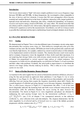
Let maintain in the same regular line two identical lumped discontinuities shifted at a distance
along the line and provided an equivalent shunt admittance (see Figure 8.1.1a) or series
impedance (see Figure 8.1.1b). EM waves moving between discontinuities and repeatedly
reflecting from and passing them acquire the frequency dependable phase shift. Clearly, the
overall magnitude of reflected and going through waves becomes frequency dependable too.
The so-called bounce diagram in Figure 8.1.1c demonstrates this effect. A set of dot-lines
drawn diagonally indicates the bouncing back and forth waves reflected consecutively from
discontinuities while the solid-lines illustrate the waves leaving the space between the
discontinuities. The shown in Figure 8.1.1c wave magnitudes and phases are obtained by
multiplying the each passing through wave by the transmission coefficient = 21 =
2 11
�1 − | | (see (7.15) of Chapter 7 for symmetrical network) or the reflection
11
coefficient after reflection from each discontinuity. The diagram demonstrates that the
11
entire magnitude of reflected and of forward wave is a sum of the infinite geometric
2
1
)
progression with the common ratio ( −2 2
11
2 − ∞ − 2 − ) (8.1)
= ∑ =0 ( ) while = (1 +
11
2
1
2
11