
Page 406 - Maxwell House
P. 406
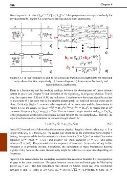
386                                                                Chapter 8


                                     ) | = | | < 1 this progression converges absolutely for
                                 −2 2  2
        Since in passive circuits |(   11
                              11
        any discontinuity. Figure 8.1.1d portrays the final closed form expressions.


        Figure 8.1.1 In-line resonator: a) and b) Reflection and transmission coefficients for shunt and
            series discontinuities, respectively, c) Bounce diagram, d) Resonator reflection   and
                                                                            1
                                   transmission   coefficients
                                              2
        There is a fascinating and far-reaching analogy between the development of linear antenna
        pattern in space (see Chapter 5) and formation of the signals   in frequency domain. That is
                                                          1,2
        why, the expressions (8.1) and (5.86) are lookswise. It explains how the output signal   reaches
                                                                             2
        its maximum of 1 the same way as the relative pattern peak, i.e. when all passing waves are in
        phase. Evidently, | | = 1 as soon as the magnitude of the numerator and the denominator in
                        2
                                                                                   th
                                                                 2

        Figure 8.1.1d are equal, i.e. (   − 2  11  2 2 11 −2  = | | . It  means that at m
                                       ) = | |
                                                               11
                                 11
        resonance frequency 2(  −  ) = 2. Here m is some integer number and  = 2/Λ
                                  11


        is the propagation coefficient at resonance defined through the wavelengths Λ . Thereby, the

        separation between discontinuities or resonator length should be
                                    = (Λ /2) +  (Λ /2)          (8.2)

                                                 11

        From (8.2) immediately follows that the resonator physical length is shorter while  11  < 0 or
        longer while  11  > 0 than Λ /2. The reader may check using the expression from Chapter 3

        that   is negative while the discontinuity is a shunt inductor ( = 1/ℒ = −/ℒ) or series
             11
        capacitor ( = 1/ = −/)  and  positive  for shunt capacitor ( = ) and series
        inductor ( = ℒ). Keep in mind that the sequence of resonance frequencies of any in-line
        resonator is in principle infinite. Sometimes, the calculation of these frequencies become
        slightly tricky because the same discontinuity might be inductive or capacitive depending on
        frequency.
        Figure 8.1.2a demonstrates the exemplary coaxial in-line resonator bounded by two capacitive
        air gaps in the center conductor. The space between conductors and inside gaps is filled up by
        Teflon ( = 2.1).  The line impedance  was  chosen 50 Ohms.  There are three  resonances

        between 0 and 10 GHz: at 2.9 GHz (Λ = 103.45/√2.1 = 71.39 mm), 6 GHz (Λ =
                                           1
                                                                                 2