
Page 408 - Maxwell House
P. 408
388 Chapter 8
Quite moderate mathematical transformations of (8.1) and (8.2) show that the unloaded quality
and relative passband 2∆/ of in-line resonator is
2∆ | 11 |
= = (8.3)
1−| 11 | 2
Here the index m marks that | | is defined at one of resonance frequencies . Evidently,
11
→ ∞ as | | → 1, i.e. the passband at least in theory might be as narrow as it is wished.
2
11
This result is expected because we did not include in our analysis the energy dissipation in
discontinuities and connected lines. However, typically the in-line resonator qualities even with
all loss included are order the of hundreds and may reach without cooling the extremely high
values depending on frequency band, line sizes, mode structure, and production quality.
Practically, it can be done exerting the resonance of TE01-mode in oversized WC. We note in
Chapter 6 that this mode losses only 2-3 dB per kilometer. The experiment shows that quality
of resonator with such mode may reach 10 and even more at ambient room temperature.
6
Concluding this section note that an in-line resonator could be developed practically with any
of discontinuities shown in Table 7.1 and 7.2. That explains the broad range of filter designs in
which those resonators are base elements.
8.2 DIRECTIONAL COUPLES AND HYBRIDS
8.2.1 Introduction
We have mentioned the directional coupler as an
item of Network Analyzer in Chapter 7.
Alongside filters and power dividers (see later)
it is probably one of the most abundant circuit
elements. The conventional equivalent circuit of
the directional coupler is shown in Figure 8.2.1a
a) as a four-port passive and reciprocal device.
The cross-lines indicate that the lines connecting
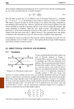
Figure 8.2.1a Directional couple circuit port 1, 2 and 3, 4 are physically connected or
mutually coupled, i.e. EM wave energy from
one line 1 to 2 leaks to another and vice versa. As a result, the signal delivered to any of coupled
ports (2, 3, and 4 if port 1 is excited, for example) is divided between other ports but not equally.
Most of the energy typically comes to the opposite port (from port 1 to port 2, for example).
However, in all cases, one port is always deeply isolated to the level of -40 dB and more relative
to energy incoming in port 1. It can be port 3 for so-called forward directional couple and
backward when it is port 4. All port enumeration is referred to Figure 8.2.1a. In general, S-
matrix of a symmetrical forward directional coupler is
11 21 31 41
= � 21 11 41 31 � (8.4)
31 41 11 21
41 31 21 11
Note that we assumed in (8.4) that a directional coupler is reciprocal, i.e. = .
