
Page 429 - Maxwell House
P. 429
MORE COMPLICATED ELEMENTS OF FEED LINES 409
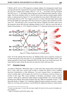
J. Butler and R. Lowe in 1961 proposed an elegant scheme of developing the simple beam
steering feed network composed only of quadrature hybrids and fixed phase shifters. In general,
the matrix has N inputs and N outputs, where N = 4, 8, 16, ... . It includes (N/2) log2N hybrids
and (N/2) log2 (N – 1) fixed phase shifters and may form N different beams pointed at various
angles. The circuit schematic of 4x4, i.e. four RF source inputs, and four antenna outputs, Butler
matrix, is demonstrated in Figure 8.3.5 and assembled from four ideal 3-dB hybrids and two
lossless phase shifters of 45°. Now suppose that port1 is excited. Then the relative phase shifts
between all output ports and inputs of the linear antenna are equal to values marked in red with
step of 45° . Note that port2, port3, and port4 stay isolated. Evidently, the Butler matrix forms
the progressive phase shift between radiating elements with 45° step that causes the shift of
primary beam maxima at ~14.5° (beam #1 in Figure 8.3.5). Injecting signal in port2 moves the
Figure 8.3.5 Phase distribution in 4x4 Butler matrix
beam ~29° in the opposite direction and so on. Multiple beams can be created by exciting two
or more beam ports at the same time. It is the remarkable fact that ideal Butler matrix is the
analog equivalent of Fast Fourier Transform (FFT), but this topic is out of this book scope. We
expect that the reader catches the idea and may draw the matrix with more ports.
8.3.7 Monopulse Concept
According to Wikipedia, “Monopulse radar is a radar system that compares the received signal
from a single radar pulse against itself in order to compare the signal as seen in multiple
directions, polarizations, or other differences. The most common form is an adaptation of
conical scanning radar which compares the return from two directions to directly measure the
location of the target. This avoids problems in decoding conventional conical scanning
9
systems , which can be confused by rapid changes in signal strength. The system also makes
jamming more difficult. Most radars designed since the 1960s are monopulse systems.” We
10
discussed shortly in Chapter 5 the technology behind the high-resolution monopulse systems
where the receiving antenna produces several differently shaped and steered in tandem beams
9 Conical scanning means "moving" the radar beam slightly off center from the antenna's boresight, and
then rotating it.
10 https://en.wikipedia.org/wiki/Monopulse_radar