
Page 464 - Maxwell House
P. 464
444 Chapter 9
3. It gives us HPBW = 0.86° that is slightly narrower than is required but is good enough to
build the initial and simplified reflector model. The promising aperture efficiency of such
field distribution is k = 0.75 that exceeds the requirements almost two times. Meanwhile,
we have to remember that on this stage of complexity reduction we omitted many other
diminishing factors like edge effect (see Chapter 3), spillover (look back at Figure 5.2.13
in Chapter 5), aperture blockage , mismatch and
6
absorption loss, etc. Besides, we omitted from the
initial consideration such system requirements as the
polarization type and cross-polarization level, power
handling, scan performance, etc. Everything should be
included during the subsequent process of expansion
to the more sophisticated computer model.
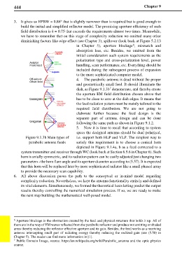
4. The parabolic antenna is dead without the proper
and geometrically small feed. It should illuminate the
dish, as Figure 9.1.3b demonstrate, and thereby create
7
the aperture EM field distribution chosen above that
has to be close to zero at the dish edges. It means that
the feed radiation pattern must be mainly tailored to the
required field distribution. We are not going to
elaborate further because the feed design is the
separate part of antenna design and can be done
following the same path as shown in Figure 9.1.2.
5. Now it is time to recall that according to system
specs the designed antenna should be dual polarized,
Figure 9.1.3b Main types of i.e. support both HLP and VLP. The simplest way to
parabolic antenna feeds satisfy this requirement is to choose a conical horn
depicted in Figure 9.1.4a, b as a feed connected to a
system transmitter and receiver through WC (look back at Section 6.5.6 in Chapter 6). Such
horn is axially symmetric, and its radiation pattern can be easily adjusted just changing two
parameters - the horn flare angle and its aperture diameter according to (5.57). It is expected
that this horn will be replaced later by more sophisticated radiator like a small phased array
to provide the necessary scan capability.
6. All above discussion paves the path to the conceptual or in-mind model regarding
complexity reduction. Nevertheless, we kept the antenna functionality entirely and defined
its vital elements. Simultaneously, we formed the theoretical basis letting predict the output
results thereby controlling the numerical simulation process. If so, we are ready to make
the next step building the mathematical well-posed model.
6 Aperture blockage is the obstruction created by the feed and physical structure that holds it up. All of
them are in the way of EM waves reflected from the parabolic reflector and produce not emitting or shaded
areas thereby reducing the reflector effective aperture and its gain. Besides, the feed works as a receiving
antenna intercepting small part of radiating energy thereby reducing the realized gain (see (5.50) in
Chapter 5). The reader can find more information in [1].
7 Public Domain Image, source: https://en.wikipedia.org/wiki/Parabolic_antenna and the optic physics
course.