
Page 476 - Maxwell House
P. 476
456 Chapter 9
The primary drawbacks of FEM technique are:
• “… The explicit expression for updating EM field in time-domain cannot be derived in the
general case. Instead, a linear system of equations has to be solved to update the field. … FEM
requires more computer resources, both in term of CPU time and memory.” [8, 9].
• The PMLs truncating the solution domain are needed in case of unbounded areas.
• FEM code is rather difficult to parallelize efficiently.
Now let come back to Perfectly Matched Layers whose presence is mandatory in many
numerical codes. It is worthy to point out that these layers are the artificial physical objects and
not the special boundary conditions as some publications treat them.
9.1.3 Perfectly Matched Layer (PML)
Frequently, the project model is open to exterior free space, i.e. unbounded, and thus some EM
waves escape to infinity that includes far-field radiation (antenna, not entirely shielded PCB,
etc.). If so, the application of explicit FDTD and many other codes becomes slightly more
complicated. For example, any FDTD computation domain should cover not only the model
area but the whole surrounding, i.e. the entire universe. Evidently, it makes the numerical
solution impractical demanding a computer with infinite memory running for unlimited time.
To go around this issue, J. P. Berenger proposed in 1994 to enclose such “open” models into
the virtual 3D cavity of a simple shape like parallelepiped or sphere with virtual walls
comprising several layers of artificial absorbing materials. Apparently, the fundamental goal
will be achieved if such material is utterly absorbing at all frequencies, polarizations, and angles
of incidence. Furthermore, it should be able to almost entirely attenuate the radiated fields on
the length of just a few cells, i.e. this extra cavity may be implemented with the minimum of
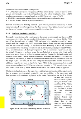
additional computer resources as depicted in Figure 9.1.18. In the corner regions, both and
are nonzero and positive. PML layers, in turn, are truncated by PEC layers (external black
box). Note that the drawing here is not in scale and PMLs’ thickness is greatly exaggerated.
The theoretical analysis shows that highly lossy artificial material meeting all the requirements
has to possess complex-valued permittivity and permeability, to be anisotropic and
heterogeneous, and sometimes unphysical by its nature. Nevertheless, the last is irrelevant
because PML cavity is
the same virtual object in
the digital domain as the
model itself. The PML is
constructed in such a
way that there is no loss
in the direction
tangential to the
interface between
internal domain and
PML. However, there is
always loss in the
direction normal to the
interface. Additionally,
Figure 9.1.18 PML layers surrounding the area of interest. the PML material