
Page 442 - Wago_AutomationTechnology_Volume3_2015_US.pdf
P. 442
767-1301
6 ETHERNET Fieldbus Coupler
440 incl. 8 digital inputs (8 x M8)
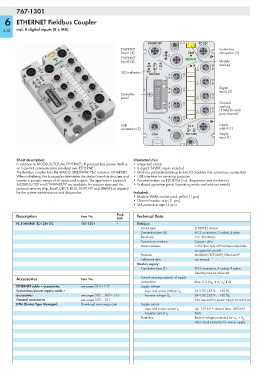
ETHERNET FC 8DI
ETHERNET System bus
Input1 (4) SBM connection (3)
1 FB 2
ETHERNET
Input2 (4) Module
MS 1 CS X marking
7 8
LED indicators NS 2
ACT/LNK X
7 6
X
12I RES 5 6
11 I B/E
9I SN X Digital
8I 2⁷ 5 4 inputs (2)
Operation 7I 2⁸ X
6I 2⁵
panel 5I 2⁴ 3 4
4I 2³
3I 2² X Channel
2I 2¹ 2
1I 2⁰ 3 marking
X
1 (1 field for each
2
port/channel)
X
1 0
USB 24 V Supply
connection (5) U LS U A output (1)
COM 767-1301 Supply
input (1)
Short description: Characteristics:
In addition to MODBUS/TCP, the ETHERNET/IP protocol has proven itself as •Integrated switch
an industrial communication standard over ETHERNET. • 8 digital 24VDC inputs included
The fieldbus coupler links the WAGO SPEEDWAY 767 system to ETHERNET. • Modular and extendable up to 64 I/O modules (via system bus connection)
When initializing, the buscoupler determines the station's module structure and • USB interface for servicing purposes
creates a process image of all inputs and outputs. The application protocols • Parametrization via FDT/DTM (incl. diagnostics and simulation)
MODBUS/TCP and ETHERNET/IP are available for process data and the • Enclosed operation panel (operating mode and address switch)
protocol services Http, BootP, DHCP, DNS, SNTP, FTP and SNMP (on request)
for the system administration and diagnostics. Included:
• Module WMB marker card, yellow (1 pcs)
• Channel marker strips (1 pcs)
• M8 protective caps (2 pcs)
Description Item No. Pack. Technical Data
Unit
FC ETHERNET 8DI 24V DC 767-1301 1 Fieldbus:
Device type ETHERNET device
Connection type (4) M12 connectors, D coded, 4 poles
Baud rate 10/100 Mbit/s
Transmission medium Copper cable
Station address 1-255 (last byte of IP address adjustable
via operation panel)
Protocols MODBUS/TCP (UDP), EtherNet/IP
Additional data see manual
Module supply:
Connection type (1) M12 connectors, A coded, 4 poles;
Derating must be observed
Accessories Item No. Current carrying capacity of supply
connections Max. 8 A (U LS : 4 A, U A : 4 A)
ETHERNET cable + accessories see pages 510 + 517 Supply voltage
System bus/power supply cable + Logic and sensor voltage U LS 24 V DC (-25 % ... +30 %)
accessories see pages 502 ... 507 + 516 Actuator voltage U A 24 V DC (-25 % ... +30 %);
General accessories see pages 520 ... 521 Also required for power supply transmission
DTM (Device Type Manager) Download: www.wago.com Supply current
typ. 125 mA + sensors (max. 400 mA)
Logic and sensor current I LS
5mA
Actuator current I A
Protection Reverse voltage protection for U LS + U A ;
short circuit protection for sensor supply