
Page 444 - Wago_AutomationTechnology_Volume3_2015_US.pdf
P. 444
767-1311
6 sercos Fieldbus Coupler
442 incl. 8 digital high-speed inputs (8 x M8)
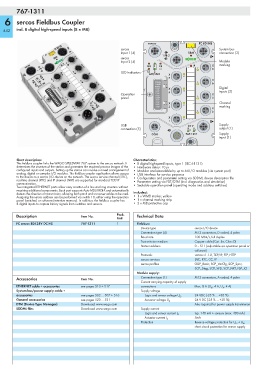
sercos FC 8DI HS
sercos System bus
Input 1 (4) SBM connection (3)
1 FB 2
sercos
Input 2 (4) Module
MS 1 CS X marking
7 8
LED indicators S3 2
ACT/LNK X
7 6
X
12I RES 5 6
11I B/E
10I DS Digital
9I 2⁸ X
8I 2⁷ 5 4 inputs (2)
Operation 7I 2⁶ X
6I 2⁵
panel 5I 2⁴ 3 4
4I 2³
3I 2² X Channel
2I 2¹ 2
1I 2⁰ 3 marking
X
1
2
X
1 0
USB 24 V Supply
connection (5) U LS U A output (1)
COM 767-1311 Supply
input (1)
Short description: Characteristics:
This fieldbus coupler links the WAGO SPEEDWAY 767 system to the sercos network. It • 8 digital high-speed inputs, type 1 (IEC 61131)
determines the structure of the station and generates the required process images of the • Hardware delay: 10 μs
configured inputs and outputs. Setting up the station can involve a mixed arrangement of • Modular and extendable by up to 64 I/O modules (via system port)
analog, digital or complex I/O modules. The fieldbus coupler application allows access • USB interface for service purposes
to the device as a sercos I/O device on the network. The sercos service channel (SVC), • Configuration and parameter setting via SDDML device description file
real-time channel (RTC) and IP channel (NRT) are supported for standard TCP/IP • Parameter setting via FDT/DTM (incl. diagnostics and simulation)
communication. • Sealable operation panel (operating mode and address switches)
Two integrated ETHERNET ports allow easy creation of a line and ring structure without
requiring additional components. Each port supports Auto MDI/MDI-X and automatically
detects the direction of transmission, allowing both patch and crossover cables to be used. Included:
Assigning the sercos address can be performed via switch 10, either using the operation • 1 x WMB marker, yellow
panel (switches) or software (retentive memory). In addition, the fieldbus coupler has • 1 x channel marking strip
8 digital inputs to capture binary signals from switches and sensors. • 2 x M8 protective cap
Description Item No. Pack. Technical Data
Unit
FC sercos 8DI 24V DC HS 767-1311 1 Fieldbus:
Device type sercos I/O device
Connection type (4) M12 connectors, D coded, 4 poles
Baud rate 100 Mbit/s, full duplex
Transmission medium Copper cable (Cat. 5e, Class D)
Station address 0 – 511 (adjustable via operation panel or
software)
Protocols sercos v1.1.2, TCP/IP, FTP, HTTP
sercos services SVC, RTC, CC, IP
sercos profiles GDP_Basic, SCP_VarCfg, SCP_Sync,
SCP_Diag, SCP_WD, SCP_NRT, FSP_IO
Module supply:
Accessories Item No. Connection type (1) M12 connectors, A coded, 4 poles
Current carrying capacity of supply
ETHERNET cable + accessories see pages 510 + 517 connections Max. 8 A (U LS : 4 A, U A : 4 A)
System bus/power supply cable + Supply voltage
accessories see pages 502 ... 507 + 516 Logic and sensor voltage U LS 24 VDC (-25 % ... +30 %)
General accessories see pages 520 ... 521 Actuator voltage U A 24 V DC (-25 % ... +30 %);
DTM (Device Type Manager) Download: www.wago.com Also required for power supply transmission
SDDML files Download: www.wago.com Supply current
typ. 140 mA + sensors (max. 400 mA)
Logic and sensor current I LS
5mA
Actuator current I A
Protection Reverse voltage protection for U LS + U A ;
short circuit protection for sensor supply