
Page 445 - Wago_AutomationTechnology_Volume3_2015_US.pdf
P. 445
6
443
sercos System bus
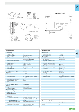
Input 1 Input 2 1: TX+ connection 1: TD+ Block diagram of an input
2: RX+ 2: TD--
3: TX– 3: RD--
4: RX– 4: RD+ Digital Input Supply
Housing: Shield 5: GND X1 ... X8
M12 D coded M12 B coded
Housing: Shield
M12
Reset
Boot / Execute Digital Inputs 1: 24 V M8
Disable Switch
Operation panel 2 8 2 7 2 6 2 5 2 4 Address 3: 0 V U LS Logic
X1 ... X8
2 2 2 3 M8 4: Input Input 0 ... 7 Error F
2 1
2 0
USB Supply
COM Input Output 1: 24 V U
1: +5 V 2: 24 V U LS
2: –Data 3: 0 V U A Module
3: +Data 4: 0 V U LS mount
4: GND A
M8 Housing: Shield M12 A coded
Technical Data Technical Data
Digital inputs: Process image: 6
Number of inputs 8 Input process image 2048 bytes
Connection type (2) M8 connectors, 3 poles Output process image 2048 bytes
Wire connection 2- or 3-wire LED indicators:
Input filter Hardware: ≤ 10 μs, software parametrizable MS: Module status LED (green/red)
depending on operating mode S3: sercos status LED (green/red)
Hardware delay up to fieldbus 10 μs (direct mode) ACT/LNK 1 : ETHERNET data
Input characteristic Type 1, acc. to IEC 61131-2 exchange/network connection LED (green)
Signal voltage (0) -3 VDC ... +5 VDC ACT/LNK 2 : ETHERNET data
Signal voltage (1) +15 V ... +30 V DC exchange/network connection LED (green)
Input wiring high-side switching CS : Fieldbus coupler status LED (green/red)
Input voltage 24 VDC (-30 VDC < U IN < +30 VDC) SBM : System bus master status LED (green/red)
Input current (typ.) 2.8 mA F: Error status LED (red)
Cable length, unshielded ≤ 30 m 0 ... 7: Input signal status LED (yellow)
Wrong connection of inputs No effect U LS + U A : Supply status LED (green)
System bus: Indicators Non-latching
Cycle time min. 250 μs Advanced features:
Number of expendable modules 64 Operating hours counter Values in [h]
Connection type (3) M12 connectors, B coded, 5 poles, High-speed inputs parametrizable, depending on operating
shielded mode (see manual)
Distance between two modules 20 m
Total extension per station 200 m
Isolation:
Channel – Channel No
U LS , U A , system bus, fieldbus 500 VDC each
Service:
Type USB standard 1.1
Connection type (5) M8 connectors, 4 poles
Standards and approvals:
Conformity marking 1
r UL 508
Configurable functions:
Fieldbus coupler see manual
Digital Inputs
Input filter (per channel) depending on operating mode
0.1/ 0.5/ 3 /15 /20 ms/ filter off
Inversion (per channel) On/off General Specifications
Online simulation (per channel) Lock/unlock, simulation value: 0/1
I/O diagnostics: Dimensions (mm) W x H x L 75 x 35.7 x 117
I/O diagnostics (per module) Short circuit of sensor supply Weight 400 g
Undervoltage (U LS + U A )