Page 448 - Wago_AutomationTechnology_Volume3_2015_US.pdf
P. 448

767-1501

   6    CANopen Fieldbus Coupler

  446   incl. 8 digital inputs (8 x M8)
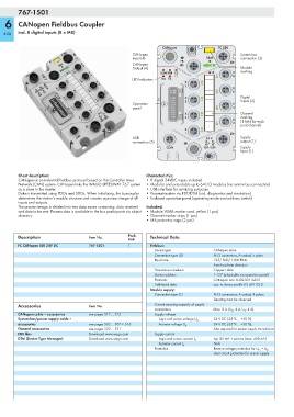

                                                                   CANopen               FC 8DI
                                                       CANopen                                    System bus
                                                       Input (4)                     SBM          connection (3)
                                                                          FB
                                                       CANopen
                                                       Output (4)                                 Module
                                                                  RUN ERR CS                   X  marking
                                                                                         7
                                                                                               8
                                                       LED indicators  RX TX
                                                                            X
                                                                            7      6
                                                                                               X
                                                                      12I RES            5     6
                                                                      11 I B/E
                                                                      9I BR  X                    Digital
                                                                      8I    5      4              Inputs (2)
                                                       Operation      7I 2⁶                    X
                                                                      6I 2⁵
                                                       panel          5I 2⁴              3     4
                                                                      4I 2³
                                                                      3I 2²  X                    Channel
                                                                      2I 2¹        2
                                                                      1I 2⁰  3                    marking
                                                                                               X
                                                                                         1        (1 field for each
                                                                                               2
                                                                                                  port/channel)
                                                                            X
                                                                            1      0
                                                       USB                           24 V         Supply
                                                       connection (5)               U LS  U A     output (1)
                                                                    COM             767-1501      Supply
                                                                                                  input (1)
        Short description:                                  Characteristics:
        CANopen is an industrial fieldbus protocol based on the Controller Area   • 8 digital 24VDC inputs included
        Network (CAN) system. CANopen links the WAGO SPEEDWAY 767 system   • Modular and extendable up to 64 I/O modules (via system bus connection)
        as a slave to the master.                           • USB interface for servicing purposes
        Data is transmitted using PDOs and SDOs. When initializing, the buscoupler   • Parametrization via FDT/DTM (incl. diagnostics and simulation)
        determines the station's module structure and creates a process image of all   • Enclosed operation panel (operating mode and address switch)
        inputs and outputs.
        The process image is divided into two data zones containing: data received   Included:
        and data to be sent. Process data is available to the bus participants via object  • Module WMB marker card, yellow (1 pcs)
        directory.                                          • Channel marker strips (1 pcs)
                                                            • M8 protective caps (2 pcs)

        Description                  Item No.        Pack.    Technical Data
                                                     Unit
        FC CANopen 8DI 24V DC        767-1501        1        Fieldbus:
                                                                Device type            CANopen slave
                                                                Connection type (4)    M12 connectors, A coded, 5 poles
                                                                Baud rate              125/ 500/ 1000 Kbits
                                                                                       Auto-baudrate detection
                                                                Transmission medium    Copper cable
                                                                Station address        1-127 (adjustable via operation panel)
                                                                Protocols              CANopen acc. to DS-301 V4.01
                                                                Additional data        acc. to device profile DS 401 V2.0
                                                              Module supply:
                                                                Connection type (1)    M12 connectors, A coded, 4 poles;
                                                                                       Derating must be observed
        Accessories                  Item No.                   Current carrying capacity of supply
                                                                connections            Max. 8 A (U LS : 4 A, U A : 4 A)
        CANopen cable + accessories  see pages 512 ... 513      Supply voltage
        System bus/power supply cable +                          Logic and sensor voltage U LS  24 V DC (-25 % ... +30 %)
        accessories                  see pages 502 ... 507 + 516  Actuator voltage U A  24 V DC (-25 % ... +30 %);
        General accessories          see pages 520 ... 521                             Also required for power supply transmission
        EDS files                    Download: www.wago.com     Supply current
        DTM (Device Type Manager)    Download: www.wago.com      Logic and sensor current I LS  typ. 85 mA + sensors (max. 400 mA)
                                                                                       5mA
                                                                 Actuator current I A
                                                                Protection             Reverse voltage protection for U LS  + U A ;
                                                                                       short circuit protection for sensor supply
   443   444   445   446   447   448   449   450   451   452   453