
Page 450 - Wago_AutomationTechnology_Volume3_2015_US.pdf
P. 450
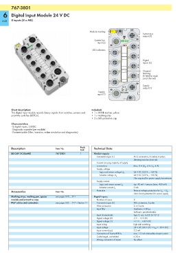
767-3801
6 Digital Input Module 24 V DC
448 8 inputs (8 x M8)
8DI
Module marking
System bus
output (3)
System bus
input (3)
X
7
8
LED indicators
X
6
7
X
5
6
Digital
X
5 4 inputs (2)
X
3
4
X Channel
2
3 marking
X
1 (1 field for each
2
port/channel)
X
0
1
Supply
24 V
U U output (1)
LS A
Supply 767-3801
input (1)
Short description: Included:
This digital input module records binary signals from switches, sensors and • 1 x WMB marker, yellow
proximity switches (BEROs). • 1 x marking strip
•2 x M8 protective cap
Characteristics:
- 8 digital inputs, 24VDC
- Diagnostic capable (per module)
- Parametrizable (filter, inversion, online simulation and diagnostics)
Description Item No. Pack. Technical Data
Unit
8DI 24V DC (8xM8) 767-3801 1 Module supply:
Connection type (1) M12 connectors, A coded, 4 poles;
Derating must be observed
Current carrying capacity of supply
connections Max. 8 A (U LS : 4 A, U A : 4 A)
Supply voltage
24 V DC (-25 % ... +30 %)
Logic and sensor voltage U LS
24 V DC (-25 % ... +30 %);
Actuator voltage U A
Also required for power supply transmission
Supply current
typ. 40 mA + sensors (max. 400 mA)
Logic and sensor current I LS
5 mA
Actuator current I A
Accessories Item No. Protection Reverse voltage protection for U LS + U A ;
short circuit protection for sensor supply
Marking strips, marking pen, spacer see pages 520 ... 521 Digital inputs:
module and protective caps Number of inputs 8
IP67 cables and connectors see pages 502 ... 517 + Section 11 Connection type (2) M8 connectors, 3 poles
Wire connection 2- or 3-wire
Input filter Hardware: ≤ 80 μs
Software: parametrizable
Input characteristic Type 2, acc. to IEC 61131-2
Signal voltage (0) -3 V ... +5 V DC
Signal voltage (1) +11 V ... +30 V DC
Input wiring high-side switching
Input voltage 24 V DC (-30 V DC < U IN < +30 V DC)
Input current (typ.) 7.3 mA
Connection of 2-wire BEROs max. 1.5 mA admissible closed current
Cable length, unshielded ≤ 30 m
Wrong connection of inputs No effect