
Page 21 - Wagp_InterfaceElectronic_Volume4_2015_US.pdf
P. 21
0
19
Max. surge current (l )
Definition of several important Smax
technical terms
The maximum surge current l Smax defines
the maximum value of a current having
Nominal operating voltage (V BN ) the 8/20μs waveform, which can flow
through the surge arrester once without
The nominal operating voltage corres ponds to destroying it.
the voltage which may be permanently
connected to the appropriate connection
terminals of the overvoltage protection modu- Protection level
le. Alternating voltages are quoted as effecti-
ve values. The protection level is the value of the
Double-deck terminal block with varistor, residual voltage occurring on the “pro-
direct connection to the DIN 35 rail Max. operating voltage (V Bmax ) tected” side of the surge arrester when
applying the rated discharge current.
Frequently, only one surge arrester is fitted for The maximum operating voltage cor responds
cost reasons. However, due to the fact that to the voltage which may be permanently
one surge arrester alone cannot optimally connected to the appropriate connection Response time (t )
ensure several protection functions, combinati- terminals without the operating properties an
ons are recommended. Care must be taken to changing or activating the individual module's
ensure that the single-stage protection devices protection elements. The response time is primarily based
are decoupled sufficiently by inductors or on the physical properties of the surge
resistors. arresters and is dependent upon the
Nominal current (I N ) wave front duration of the surge voltage.
The nominal current corresponds to the cur- WAGO's data refers to a voltage rise of
In addition to single-stage surge arresters, 1kV/μs.
WAGO AUTOMATION also offers multi- rent which may permanently flow through the
stage surge arresters, combining components connection terminals of the overvoltage
for different applications. These pluggable protection device.
modules are snapped into “carrier” terminal
blocks. These are DIN rail-mounted and offer Nominal discharge current (I SN )
secure and maintenance-free
®
CAGE CLAMP terminations for conductors The nominal discharge current is the
2
2
0.08mm /AWG 28 to 2.5mm /AWG 14. maximum value of a current having the
8/20 μs waveform
(DIN VDE 0432/10.78 part 3), which can
flow through the surge arrester five times
within a time period of 30 seconds (VDE) wit-
hout destroying it.
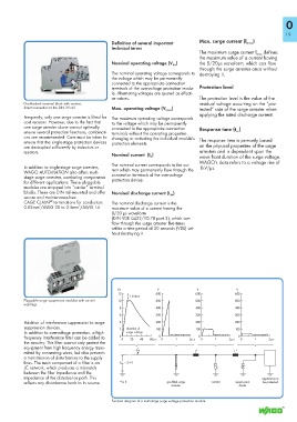
kV V V V
12 600 600 600
1 kV/ms
Pluggable surge suppression modules with on-unit 10 500 500 500
warnings
8 400 400 400
6 300 300 300
Addition of interference suppres sion to surge 4 200 200 200
suppression devices. 2 duration of 100 100 100
In addition to overvoltage protection, a high surge voltage
frequency interference fil ter can be added to 0 0 20 40 60μ s 0 0 1 2μ s 0 0 1 2μ s 0 0 1 2μ s
the circuitry. This filter cannot only protect the
equipment from high frequency energy trans-
mitted by connecting wires, but also prevents L a L a
a transmission of disturbances to the supply
lines. The main component of a filter is an V DC = 24 V
LC network, which produces a mismatch
between the filter impedance and the
impedance of the disturbance path. This applicance to
reflects any disturbance back to its source. a) or R gas-filled surge varistor suppression be protected
arrester diode
Function diagram of a multi-stage surge voltage protection module