
Page 332 - Parker - Parker Pneumatic
P. 332
PDE2600PNUK
Parker Pneumatic Origa OSP-E Electric Linear Actuators
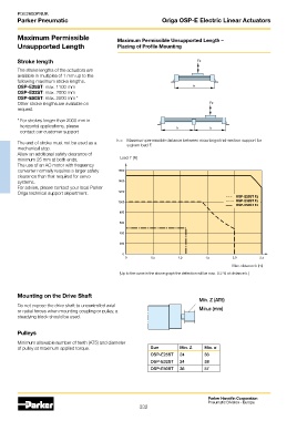
Maximum Permissible Maximum Permissible Unsupported Length –
Unsupported Length Placing of Profile Mounting
Stroke length
The stroke lengths of the actuators are
available in multiples of 1 mm up to the
following maximum stroke lengths.
OSP-E25ST: max. 1100 mm
OSP-E32ST: max. 2000 mm
OSP-E50ST: max. 2500 mm *
Other stroke lengths are available on
request.
* For strokes longer than 2000 mm in
horizontal applications, please
contact our customer support
k = Maximum permissible distance between mountings/mid-section support for
The end of stroke must not be used as a a given load F.
mechanical stop.
Allow an additional safety clearance of
minimum 25 mm at both ends. Load F [N]
The use of an AC motor with frequency
converter normally requires a larger safety
clearance than that required for servo
systems.
For advise, please contact your local Parker
Origa technical support department.
– . – OSP-E25ST Fz
------ OSP-E32ST Fz
OSP-E50ST Fz
Max. distance k [m]
(Up to the curve in the above graph the deflection will be max. 0.2 % of distance k.)
Mounting on the Drive Shaft
Min. Z (AT5)
Do not expose the drive shaft to uncontrolled axial
or radial forces when mounting coupling or pulley, a Min.ø (mm)
steadying block should be used.
Pulleys
Minimum allowable number of teeth (AT5) and diameter
of pulley at maximum applied torque. Size Min. Z Min. ø
OSP-E25ST 24 38
OSP-E32ST 24 38
OSP-E50ST 36 57
Parker Hannifin Corporation
Pneumatic Division - Europe
332