
Page 267 - Wago_PCB_TerminalBlocksConnectors_Volume2_2015_US
P. 267
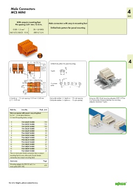
Male Connectors
           MCS MINI                                                                                                4
                                                                                                                   265


                With snap-in mounting feet
               Pin spacing: 3.81 mm / 0.15 in.  Male connectors with snap-in mounting feet
                                              Drilled hole pattern for panel mounting
             0.08–1.5 mm 2     28–14 AWG
          160 V/2.5 kV/2  10 A  300 V/10 A


                                                                                                                    4
                          <__12 __><_ 10,3 _ >
                                              Drilled hole pattern for panel mounting
                                        _>  >  __
                                       >  _
           <           4,5              <_12,9  <_ 13,4     3,5
           >4,35                       <8,5  _  _  _  2-pole
                        < >  4,15
                            <____                      <7>
                          <__12 __>
                         <______ 22,4 ______>             3,5  +0,1
                        7,62  >  )  (___  3,  <_ 1  _
                                       >  _____ >  _____ >  3 or more
                                              poles
                     3,81  __>  >       _  _  L         <____________ L ___________>
                                      2,8  ___)  <_____ L 1  _  <_____  _
                      3,81  >  ___  _)
                        1,4  >  __     >
         L = (pole no. – 1) x pin spacing + 5.9 mm + 0.45 mm   Even pole number : L = (pole no. – 2) x pin spacing   Using two DIN 35-rail mounting adapters (209-137) for
         L = L – 0.45 mm                      Odd pole number: L = (pole no. – 1) x pin spacing  3 or more poles. Distance between two mounting
          1
                                                                                 adapters: maximum 7 poles.

          Pole No.  Item No.         Pack. Unit
          Male connector with snap-in mounting feet,
          for 0.6–1.2 mm plate thickness,
          3.5 mm Ø mounting holes, orange
           2        734-332/018-000      100
           3        734-333/018-000      100
           4        734-334/018-000      100
           5        734-335/018-000      50
           6        734-336/018-000      50
           8        734-338/018-000      50
           9        734-339/018-000      50
          10        734-340/018-000      50
          12        734-342/018-000      50
          14        734-344/018-000      25
          16        734-346/018-000      25
          18        734-348/018-000      25
          19        734-349/018-000      25
          20        734-350/018-000      25
          Three or more pole female connectors have a snap-in
          mounting foot at every other pole (2-pole female
          connectors/two snap-in mounting feet)
          Accessory                     Page
          Mounting adapter for DIN 35 rail, 3 or   479
          more poles (209-187)


         For other lengths, please contact factory.