
Page 338 - Wago_PCB_TerminalBlocksConnectors_Volume2_2015_US
P. 338
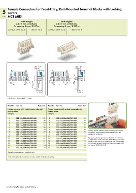
Female Connectors for Front-Entry, Rail-Mounted Terminal Blocks with Locking
   5 Levers
   336 MCS MIDI

                   With straight                       With angled
               0.6 x 1 mm contact pins            0.6 x 1 mm contact pins
             Pin spacing: 5 mm / 0.197 in.      Pin spacing: 5 mm / 0.197 in.

        320 V/4 kV/3  12 A  300 V/ 15 A    320 V/4 kV/3  12 A   300 V/ 15 A


                                 <  6 <                              <  6 <
                               2,2                                2,2
                               __>  <                             __>  <
                                        ___ _ 21,6  ____>          <       ___ _ 21,6  ____>

                                <9,8>   <                                  <

       >  8,2 <     >  5  •  7,6  <        >  8,2 <    >  5  •  7,6  <  9,8  ___>
            <______  L  ______>  <_ 14,5 _>     <______  L  ______>
                               1,5  <                             1,5  <
                                                                  __>
                               __>
                                 <10,8>                              <10,8>
                                 <11,6 >                             <11,6 >
       L = (pole no. x pin spacing) + 1.5 mm


        Pole No.  Item No.        Pack. Unit  Pole No.  Item No.     Pack. Unit
        Female connector with straight contact pins and   Female connector with angled contact pins and
        locking levers,                    locking levers,
        light gray                         light gray

         2     722-132/005-000/039-000  100   2   722-232/005-000/039-000  100
         3     722-133/005-000/039-000  50   3    722-233/005-000/039-000  50
         4     722-134/005-000/039-000  50   4    722-234/005-000/039-000  50
         5     722-135/005-000/039-000  50   5    722-235/005-000/039-000  50
         6     722-136/005-000/039-000  50   6    722-236/005-000/039-000  50
         7     722-137/005-000/039-000  50   7    722-237/005-000/039-000  50  Locking devices prevent side-mounted or top-mounted
         8     722-138/005-000/039-000  50   8    722-238/005-000/039-000  50  connectors from loosening when tensile forces are
         9     722-139/005-000/039-000  25   9    722-239/005-000/039-000  25  exerted on conductors.
        10     722-140/005-000/039-000  25  10    722-240/005-000/039-000  25
        11     722-141/005-000/039-000  25  11    722-241/005-000/039-000  25  For locking device operation at least 20 mm of space
                                                                              is required for each connector. When fitting touch-proof
        12     722-142/005-000/039-000  25  12    722-242/005-000/039-000  25  female connectors on the distribution side of front-entry,
        14     722-144/005-000/039-000  25  14    722-244/005-000/039-000  25  rail-mounted terminal blocks, the nominal voltage shall
        16     722-146/005-000/039-000  10  16    722-246/005-000/039-000  10  not exceed 320 V/4 kV/3.
        20     722-150/005-000/039-000  10  20    722-250/005-000/039-000  10
        2-pole female connectors - one latch only

        11 to 20-pole female connectors are only suitable for factory assembly.


       For other lengths, please contact factory.