
Page 357 - Wago_PCB_TerminalBlocksConnectors_Volume2_2015_US
P. 357
"
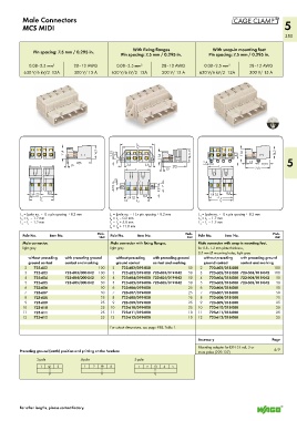
Male Connectors
MCS MIDI 5
355
With fixing flanges With snap-in mounting feet
Pin spacing: 7.5 mm / 0.295 in. Pin spacing: 7.5 mm / 0.295 in. Pin spacing: 7.5 mm / 0.295 in.
0.08–2.5 mm 2 28–12 AWG 0.08–2.5 mm 2 28–12 AWG 0.08–2.5 mm 2 28–12 AWG
630 V/6 kV/2 12A 300 V/ 15 A 630 V/6 kV/2 12A 300 V/ 15 A 630 V/6 kV/2 12A 300 V/ 15 A
<_________ _________> >
L 6
<________ ________>
(_ 1 4,3 _) L 5 > (_ 1 4,3 _)
>
11,4 3,55 ___> __> 11,4 (_ 1 4,3 _) 4,5 __> 11,4
2,6
1,5
<____ 27,5 ____> > > 3,4 2,6 < 2,4 < < < <__ < 12,15 < 5
__> <
<
1,5
<______ _______> < <__ > <__ __> < <____ 27,5 ____> <______ _______> <____ 27,5 ____>
L 1
L 1
1,5
<______ _______> < <__
L 1
2,5 > <__ >
> 5,1 > > 9,8 7
> 5 7,5 < 0,3 < > > 5 7,5 < 0,3 <
__>
__>
0,3
<______ ______> > 5 7,5 < __> < > <______ ______>
L 2
L 2
<______ ______> <______ ______> <______ ______>
L 3
L 3
L 4
L = (pole no. – 1) x pin spacing + 8.2 mm L = (pole no. – 1) x pin spacing + 8.2 mm L = (pole no. – 1) x pin spacing + 8.2 mm
1
1
1
L = L – 1.7 mm L = L – 0.2 mm L = L – 1.7 mm
1
2
4
1
1
2
L = L – 1.2 mm L = L + 5.8 mm L = L – 1.2 mm
1
4
1
3
3
5
L = L + 11.8 mm
6
4
Pole No. Item No. Pack. Pole No. Item No. Pack. Pole No. Item No. Pack.
Unit
Unit
Unit
Male connector, Male connector with fixing flanges, Male connector with snap-in mounting feet,
light gray light gray for 0.6–1.2 mm plate thickness,
3.5 mm Ø mounting holes, light gray
without preceding with preceding ground without preceding with preceding ground without preceding with preceding ground
ground contact contact and marking ground contact contact and marking ground contact contact and marking
2 723-602 100 2 723-602/019-000 50 2 723-602/018-000 100
3 723-603 723-603/000-042 100 3 723-603/019-000 723-603/019-042 50 3 723-603/018-000 723-603/018-042 100
4 723-604 723-604/000-042 50 4 723-604/019-000 723-604/019-042 50 4 723-604/018-000 723-604/018-042 50
5 723-605 723-605/000-042 50 5 723-605/019-000- 723-605/019-042 50 5 723-605/018-000 723-605/018-042 50
6 723-606 50 6 723-606/019-000 25 6 723-606/018-000 50
7 723-607 50 7 723-607/019-000 25 7 723-607/018-000 50
8 723-608 25 8 723-608/019-000 25 8 723-608/018-000 25
9 723-609 25 9 723-609/019-000 25 9 723-609/018-000 25
10 723-610 25 10 723-610/019-000 25 10 723-610/018-000 25
11 723-611 25 11 723-611/019-000 10 11 723-611/018-000 25
12 723-612 25 12 723-612/019-000 10 12 723-612/018-000 25
3
3
1
For cutout dimensions, see page 488, Table 1.
Accessory Page
1 3 3 1 2 3 4 Mounting adapter for DIN 35 rail, 3 or
Preceding ground (earth) position and printing on the headers: more poles (209-137) 479
3-pole 4-pole 5-pole
1 3 3 1 2 3 4 1 2 3 4 5
1 2 3 4 1 2 3 4 5
For other lengths, please contact factory.
2
5
1
3
4