
Page 360 - Wago_PCB_TerminalBlocksConnectors_Volume2_2015_US
P. 360
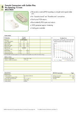
Female Connectors with Solder Pins
   5 Pin Spacing: 7.5 mm
   358 MCS MIDI
                                              ●  Horizontal or vertical PCB mounting via straight and angled solder
                                                pins
                                              ●  For “board-to-board” and “board-to-wire” connections

                                              ●  Touch-proof PCB outputs

                                              ●  Easy-to-identify PCB inputs and outputs
                                              ●  100% protected against mismating

                                              ●  Coding pins available


        Technical data:

        Pin Spacing               7.5 mm                                                   Derating Curve
                                  0.295 in.
        Ratings per            IEC/EN 60664-1                                   722-832 female connector with 723-602 male header
                                                                                Pin spacing: 7.5 mm / Conductor size: 2.5 mm  “f-st”
                                                                                                           2
        Overvoltage category   III  III   II                                     Based on: EN 60512-5-2 / Reduction factor: 0.8
        Pollution degree       3    2     2                                     Current in A
        Rated voltage        500 V  630 V 1000 V                                45
        Rated surge voltage   6 kV  6 kV  6 kV                                  40
        Nominal current       12 A  12 A  12 A                                  35
        Approvals per             UL/CSA                                        30
        Use group UL 1059      B    C     D
        Rated voltage         300 V  –   300 V                                  25
        Nominal current UL    15 A  –    10 A                                   20
        Nominal current CSA   15 A  –    10 A                                   15
        The MCS MIDI connection system is UL 1977 approved and capable of up to 600 V for factory wiring.  10
                                                                                 5
        Solder pin data:                                                         0  10  20  30  40  50  60  70  80 85
        Solder pin: length/width    5 mm / 0.6 x 1 mm                                        Ambient operating temperature in °C
        Solder pin: drilled hole diameter  1.3 +0.1  mm                           2-,  4-,  6-,  12-pole  Conductor rated current


        Material data:                                                          MCS MIDI accessories:      Pages:
        Material group              I
        Insulating material         Polyamide 6.6 (PA 6.6)                      Marking accessories     570 – 573
          Flammability rating per UL 94  0V                                     Test plug adapter            478
        Lower/Upper limit temperature  -60 °C / +85 °C                          Test plug                    568
        Contact material            Copper alloy
        Contact plating             tin-plated


       Additional approvals and corresponding ratings can be found at www.wago.com.   For additional technical information, see Section 13.