Page 363 - Wago_PCB_TerminalBlocksConnectors_Volume2_2015_US
P. 363

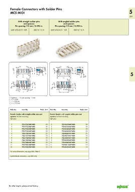
Female Connectors with Solder Pins
          MCS MIDI                                                                                                 5
                                                                                                                   361

                 With straight solder pins          With angled solder pins
                      and spacers                        and spacers
              Pin spacing: 7.5 mm / 0.295 in.     Pin spacing: 7.5 mm / 0.295 in.

           630 V/6 kV/2  12A   300 V/ 15 A    630 V/6 kV/2  12A   300 V/ 15 A


                  2,6   3,4                          2,6    3,4
               >  <__   __>  <   <_ 18,25_>  5 <  >  <__    __>  <   <_ 18,25_>
             2,6  <__        3,55  <___  <  11,6  3,95  <___  2,6  <__  3,55  <___  <  11,6
              >                                   >                                                                 5
                                                                     9,8
                 <_____ L 1 _____>  >  >  9,8  >                  >  >  ___>  <
                <_____ _ L 2 _______>  ___>  <       <_____ L 1 _____>     4,4
               <________L 3_________>               <_____ _ L 2 _______>  >  <__
                        2                          <________L 3_________>
                        >  <                                2 >  <
             2,6                4,9
            <  <__            <  <__             2,6  <__         <  4,9
                              7                 <                 7  <__
           5,1  _>  >         >  >             5,1  _>  >  2,6    >  >
                  2,6 > 7,5 5 <
               >  <__    >  <_ 3,4                >  <__  > 7,5  5  <  3,4
                  <____L _ _____>                            >  <__
                                                     <____L ____>
         L = (pole no. – 1) x pin spacing + 5 mm
         L  = L + 3 mm
          1
         L  = L + 8.8 mm
          2
         L  = L +14.8 mm
          3
          Pole No.  Item No.         Pack. Unit  Pole No.  Item No.     Pack. Unit
          Female header with straight solder pins and    Female header with angled solder pins and
          spacers, for flush mounting,       spacers, for flush mounting,
          light gray                         light gray

           2        722-732/047-000      50   2        722-832/047-000      50
           3        722-733/047-000      50   3        722-833/047-000      50
           4        722-734/047-000      50   4        722-834/047-000      50
           5        722-735/047-000      50   5        722-835/047-000      50
           6        722-736/047-000      25   6        722-836/047-000      25
           7        722-737/047-000      25   7        722-837/047-000      25
           8        722-738/047-000      25   8        722-838/047-000      25
           9        722-739/047-000      25   9        722-839/047-000      25
          10        722-740/047-000      25  10        722-840/047-000      25
          11        722-741/047-000      10  11        722-841/047-000      10
          12        722-742/047-000      10  12        722-842/047-000      10
          For cutout dimensions, see page 490, Table 3.

          2-pole female connectors - one latch only


         For other lengths, please contact factory.
   358   359   360   361   362   363   364   365   366   367   368