
Page 73 - Gefran - Inverter system and power supply unit (ADV200 Drive family)
P. 73
Gefran Spa - Drive & Motion Control Unit • www.gefran.com 73
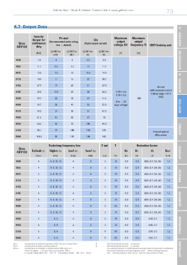
4.7 Output Data
Inverter ADV200 - 4
Output for Pn mot I2n Maximum Maximum
output
output
Sizes continuous (Recommended motor rating, (Rated output current) voltage U2 frequency f2 IGBT braking unit
ADV100 duty fsw = default)
@400 Vac @460 Vac @400 Vac @460 Vac
[kVA] [V] [Hz]
[kW] [Hp] [A] [a]
1040 7.6 4 5 9.5 8.6 ADV200-DC
1055 11.1 5.5 7.5 13 11.7
2075 13.9 7.5 10 16.5 14.9
2110 19.4 11 15 23 20.7
3150 27.7 15 20 31 27.9 ADV200 - 6
Internal
(with external resistor);
3185 32.6 18.5 25 38 34.2 0.98 x Uln braking torque 150 %
0.98 x Uln
3220 36.7 22 30 46 41.4 500 MAX
(Uln = AC
4300 36.7 30 40 62 55.8 input voltage) ADV100
4370 44.3 37 50 75 67.5
4450 51.3 45 60 87 78
5550 69.3 55 75 105 94.5
5750 99.1 75 100 150 135 ADV80
External optional
(BUy series)
5900 118.5 90 125 180 162
Switching frequency fsw F out T Reduction factor
Sizes
ADV100 Default (5) Higher (5) lswf (6) hswf (6) Kv Kt Kf Kalt AFE200
[KHz] [KHz] [KHz] [KHz] [Hz] [°C] (1) (2) (3) % (4)
1040 4 6. 8. 10. 12 4 8 3 70 0.9 0.9 0.85; 0.7; 0.6; 0.5 1.2
1055 4 6. 8. 10. 12 4 8 3 75 0.9 0.9 0.85; 0.7; 0.6; 0.5 1.2
FFE200
2075 4 6. 8. 10. 12 4 8 3 70 0.9 0.9 0.85; 0.7; 0.6; 0.5 1.2
2110 4 6. 8. 10. 12 4 8 3 70 0.9 0.9 0.85; 0.7; 0.6; 0.5 1.2
3150 4 6. 8. 10. 12 4 8 3 70 0.9 0.9 0.85; 0.7; 0.6; 0.5 1.2
3185 4 6. 8. 10. 12 4 8 3 75 0.9 0.9 0.85; 0.7; 0.6; 0.5 1.2
3220 4 6. 8. 10. 12 4 8 3 75 0.9 0.9 0.85; 0.7; 0.6; 0.5 1.2 SMB200
4300 4 6. 8. 10. 12 4 8 3 65 0.9 0.9 0.85; 0.7; 0.6; 0.5 1.2
4370 4 6. 8. 10. 12 4 8 3 70 0.9 0.9 0.85; 0.7; 0.6; 0.5 1.2
4450 4 6. 8 4 8 3 75 0.9 0.9 0.85; 0.7 1.2
5550 4 6. 8 4 8 3 70 0.9 0.9 0.85; 0.7 1.2 PROGRAM.
5750 4 6. 8 4 8 5 65 0.9 0.9 0.85; 0.7 1.2
5900 4 6. 8 4 8 5 65 0.9 0.9 0.85; 0.7 1.2
(2) Kt : Derating factor for ambient temperature of 50°C (1% every °C above 40°C) 5) PAR 568 Switching freq mode = [0] Constant
(3) Kf : Derating factor for higher switching frequency 6) PAR 568 Switching freq mode = [1] Variable
(4) Kalt : Derating factor for installation at altitudes above 1000 meters a.s.l. The switching frequency is variable between two levels (hswf and lswf) which are defined by APPENDIX
Value to be applied = 1.2% each 100 m increase above 1000 m. the heatsink temperature and output frequency (hswf = Default switching frequency,
For example: Altitude 2000 m, Kalt = 1.2% * 10 = 12% derating; In derated = (100 - 12) % = 88 % In lswf = Switching frequency when Fout or T reach the values showed in table).