
Page 319 - Wago_Rail-MountedTerminalBlockSystems_Volume1_2015_US.pdf
P. 319
"
X-COM -SYSTEM
®
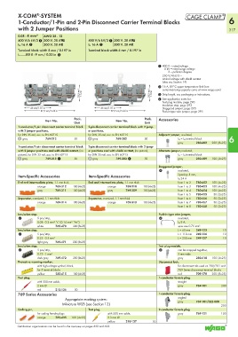
1-Conductor/1-Pin and 2-Pin Disconnect Carrier Terminal Blocks 6
with 2 Jumper Positions 317
0.08 - 4 mm² AWG 28 - 12
400 V/6 kV/3 1 300 V, 20 AU 400 V/6 kV/3 1 300 V, 20 AU
I N 16 A 2 300 V, 20 A2 I N 16 A 2 300 V, 20 A2
Terminal block width 5 mm / 0.197 in Terminal block width 5 mm / 0.197 in
L 8 - 9 mm / 0.33 in 3
1 400 V = rated voltage
6 kV = rated surge voltage
3 = pollution degree
250 V/4 kV/3 =
ominal voltage with shield contact
(also see Section 14)
2 16 A, 85°C upper temperature limit (see
<_ 28,5 mm/ _> 1.12 in <_ 28,5 mm/ _> 1.12 in 3 Strip length, see packaging or instructions.
current-carrying capacity curve at www.wago.com)
4 See application notes for:
Test plug module, page 290
Insulation stop, page 293
<___ 46 mm/1.81 in ___> <___ 46 mm/1.81 in ___> Staggered jumper, page 295
<____________ 87,5 mm/3.44 in _____________> <____________ 87,5 mm/3.44 in _____________> Push-in type wire jumper, page 295
Pack. Pack. Accessories
Item No. Item No.
Unit Unit
1-conductor/1-pin disconnect carrier terminal block 2-pin disconnect carrier terminal block with 2 jump-
with 2 jumper positions, er positions,
for DIN 35 rail, acc. to EN 60715 for DIN 35 rail, acc. to EN 60715 Adjacent jumper, insulated,
gray 769-212 50 gray 769-202 50 I N = I N terminal block 6
gray 280-402 200 (8x25)
1-conductor/1-pin disconnect carrier terminal block 2-pin disconnect carrier terminal block with 2 jump-
with 2 jumper positions and with shield contact, (no er positions and with shield contact, (no picture), Alternate jumper, insulated,
picture), for DIN 35 rail, acc. to EN 60715 for DIN 35 rail, acc. to EN 60715 I N = I N terminal block
gray 769-213 1 50 gray 769-203 1 50 gray 280-409 100 (4x25)
Staggered jumper,
4 insulated,
Item-Specific Accessories Item-Specific Accessories Spacing: 5 mm,
I N 24 A
End and intermediate plate, 1.1 mm thick End and intermediate plate, 1.1 mm thick from 1 to 2 780-452 100 (4x25)
orange 769-312 100 (4x25) orange 769-310 100 (4x25) from 1 to 3 780-453 100 (4x25)
gray 769-311 100 (4x25) gray 769-309 100 (4x25) from 1 to 4 780-454 100 (4x25)
from 1 to 5 780-455 50 (2x25)
Separator, oversized, 1.1 mm thick Separator, oversized, 1.1 mm thick from 1 to 6 780-456 50 (2x25)
orange 769-314 100 (4x25) orange 769-313 100 (4x25) from 1 to 7 780-457 50 (2x25)
from 1 to 8 780-458 50 (2x25)
Insulation stop, Push-in type wire jumper,
4 5 pcs/strip, 4 insulated,
0.08 - 0.2 mm² “s” (0.14 mm² “f-st”) I N 9 A,
white 769-470 200 (8x25) wire size 0.75 mm²
Insulation stop, L = 60 mm 249-125 10
4 5 pcs/strip, L = 110 mm 249-126 10
0.25 - 0.5 mm² L = 250 mm 249-127 10
light gray 769-471 200 (8x25)
Insulation stop, Test plug module,
4 5 pcs/strip, 4 can be snapped together,
0.75 - 1 mm² 5 mm wide
dark gray 769-472 200 (8x25) gray 280-418 100 (4x25)
Protective warning marker, Disconnect lock,
with high-voltage symbol, black, for disconnect tab used on 280/281 and
for 5 terminal blocks 769 Series disconnect terminal blocks
yellow 280-415 100 (4x25) red 709-170 200 (8x25)
Test plug, 1-conductor female plug,
with 500 mm cable, straight
2 mm Ø gray 769-101 200
red 210-136 50
769 Series Accessories 1-conductor female plug,
Appropriate marking system: angled
Miniature WSB (see Section 13) gray 769-101/022-000 200
Coding pin, Test plug, 2-conductor female plug
for coding female plugs with 500 mm cable, gray 769-121 100
orange 769-435 100 (4x25) 2.3 mm Ø
yellow 210-137 50
Certification organizations can be found in the overview on pages 622 and 623.