
Page 616 - Wago_Rail-MountedTerminalBlockSystems_Volume1_2015_US.pdf
P. 616
14 – Continued –
General Technical Information
614 for Electrical Equipment in Hazardous Environments
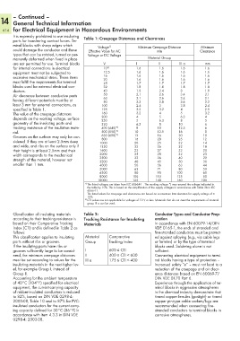
It is expressly prohibited to use insulating Table 1: Creepage Distances and Clearances
parts for transferring contact forces. Ter-
minal blocks with sharp edges which Voltage Minimum Creepage Distance Minimum
1)
could damage the conductor and those Effective Value for AC mm Clearance
types that can be rotated, turned or per- Voltage or DC Voltage
manently deformed when fixed in place Material Group
are not permitted for use. Terminal blocks V I II III a mm
for internal connections in electrical 10 2) 1.6 1.6 1.6 1.6
equipment must not be subjected to 12.5 1.6 1.6 1.6 1.6
excessive mechanical stress. These items 16 1.6 1.6 1.6 1.6
1.6
1.6
1.6
1.6
20
must fulfill the requirements for terminal 25 1.7 1.7 1.7 1.7
blocks used for external electrical con- 32 1.8 1.8 1.8 1.8
ductors. 40 1.9 2.4 3 1.9
Air clearance between conductive parts 50 2.1 2.6 3.4 2.1
63
2.6
2.1
3.4
2.1
having different potentials must be at 80 2.2 2.8 3.6 2.2
least 3 mm for external connections, as 100 2.4 3 3.8 2.4
specified in Table 1. 125 2.5 3.2 4 2.5
The value of the creepage distances 160 3.2 4 5 3.2
depends on the working voltage, surface 200 4 5 6.3 4
6.3
250
5
5
8
geometry of the insulating parts and 320 6.3 8 10 6
tracking resistance of the insulation mate- 400 (440)* ) 8 10 12.5 6
rial. 500 (550)* ) 10 12.5 16 8
Grooves on the surface may only be con- 630 (690)* ) 12 16 20 10
12
25
800
20
16
sidered if they are at least 2.5mm deep 1000 20 25 32 14
and wide, and ribs on the surface only if 1250 22 26 32 18
their height is at least 2.5mm and their 1600 23 27 32 20
width corresponds to the mechanical 2000 25 28 32 23
strength of the material, however not 2500 32 36 40 29
50
3200
45
36
40
smaller than 1 mm. 4000 50 56 63 44
5000 63 71 80 50
6300 80 90 100 60
8000 100 110 125 80
10000 125 140 160 100
1) The listed voltages are taken from IEC 60664-1 . The working voltage *) may exceed the voltage indicated in
the table by 10%. This is based on the simplification of the supply voltages in accordance with Table 3b in IEC
60664-1.
The listed values for creepage and clearances are based on a maximum limit deviation for supply voltage of ±
10%.
2) CTI values are not applicable for voltages of 10 V or less. Materials that do not meet the requirements of material
group III a can be used.
Classification of insulating materials Table 2: Conductor Types and Conductor Prep-
according to their tracking resistance is Tracking Resistance for Insulating aration
based on their Comparative Tracking Materials In accordance with EN 60079-14/DIN
Index (CTI) and is defined in Table 2 as VDE 0165-1, the ends of stranded and
follows: fine-stranded conductors must be protect-
This classification applies to insulating Material Comparative ed against splaying (e.g., via cable lugs
parts without ribs or grooves. Group Tracking Index or ferrules) or by the type of terminal
If the insulating parts have ribs or blocks used. Soldering alone is not
grooves sufficiently large to be consid- I 600 ≤ CTI sufficient.
ered, the minimum creepage distances II 400 ≤ CTI < 600 Connecting electrical equipment to termi-
must be set according to values for the III a 175 ≤ CTI < 400 nal blocks having a type of protection –
insulating materials in the next-higher lev- Increased safety “e” – must not lead to a
el, for example Group I, instead of reduction of the creepage and air clear-
Group II. ance distances based on EN 60069-7/
Accounting for the ambient temperature DIN VDE 0170 Part 6.
of 40°C (104°F) specified for electrical Experience through the application of ter-
equipment, the current-carrying capacity minal blocks in aggressive atmospheres
of rubber-insulated conductors is reduced in the chemical industry demonstrate that
to 82%, based on DIN VDE 0298-4: tinned copper ferrules (gastight) or tinned
2003-08, Table 10 and to 87% for PVC- copper pin-type cable sockets/lugs are
insulated conductors for the current-carry- recommended when connecting fine-
ing capacity defined for 30°C (86°F) in stranded conductors to terminal blocks in
accordance with Item 4.3.3 in DIN VDE corrosive atmospheres.
0298-4: 2003-08.