
Page 319 - Mechatronics with Experiments
P. 319
Printer: Yet to Come
October 28, 2014 11:15 254mm×178mm
JWST499-Cetinkunt
JWST499-c05
ELECTRONIC COMPONENTS FOR MECHATRONIC SYSTEMS 305
v 2
+
–
R R
R
R X – + v 0
v 0 = 1+ 2R v 1 − v
R Rx 2
R R
v 1 + -
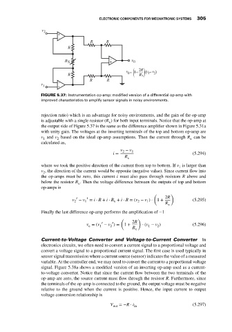
FIGURE 5.37: Instrumentation op-amp: modified version of a differential op-amp with
improved characteristics to amplify sensor signals in noisy environments.
rejection ratio) which is an advantage for noisy environments, and the gain of the op-amp
is adjustable with a single resistor (R ) for both input terminals. Notice that the op-amp at
x
the output side of Figure 5.37 is the same as the difference amplifier shown in Figure 5.31a
with unity gain. The voltages at the inverting terminals of the top and bottom op-amp are
v and v based on the ideal op-amp assumptions. Then the current through R can be
1 2 x
calculated as,
v − v 1
2
i = (5.294)
R
x
where we took the positive direction of the current from top to bottom. If v is larger than
1
v , the direction of the current would be opposite (negative value). Since current flow into
2
the op-amps must be zero, this current i must also pass through resistors R above and
below the resistor R . Then the voltage difference between the outputs of top and bottom
x
op-amps is
( )
′
v − v ′ = i ⋅ R + i ⋅ R + i ⋅ R = (v − v ) ⋅ 1 + 2R (5.295)
2 1 x 2 1
R
x
Finally the last difference op-amp performs the amplification of −1
( )
2R
′
′
v = (v − v ) = 1 + ⋅ (v − v ) (5.296)
1
2
1
o
2
R x
Current-to-Voltage Converter and Voltage-to-Current Converter In
electronics circuits, we often need to convert a current signal to a proportional voltage and
convert a voltage signal to a proportional current signal. The first case is used typically in
sensor signal transmission where a current source (sensor) indicates the value of a measured
variable. At the controller end, we may need to convert the current to a proportional voltage
signal. Figure 5.38a shows a modified version of an inverting op-amp used as a current-
to-voltage converter. Notice that since the current flow between the two terminals of the
op-amp are zero, the source current must flow through the resistor R. Furthermore, since
the terminals of the op-amp is connected to the ground, the output voltage must be negative
relative to the ground when the current is positive. Hence, the input current to output
voltage conversion relationship is
V =−R ⋅ i (5.297)
out in