
Page 320 - Mechatronics with Experiments
P. 320
JWST499-Cetinkunt
JWST499-c05
306 MECHATRONICS Printer: Yet to Come October 28, 2014 11:15 254mm×178mm
f
i
i
(a) (b)
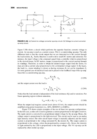
FIGURE 5.38: (a) Current to voltage converter op-amp circuit. (b) Voltage to current converter
op-amp circuit.
Figure 5.38b shows a circuit which performs the opposite function: converts voltage to
current. An op-amp is used as a current source. This is a noninverting op-amp. The only
difference here is that the circuit output that we are interested in is the current through
the load resistor, R . Such a function is used to drive small DC motors and solenoids. For
L
instance, the input voltage is the command signal from a controller which is proportional
to the desired torque. In DC motors, torque is proportional to the current passing through
its windings. Therefore, in order to obtain the desired torque output from the motor, we
must provide a current value proportional to the commanded voltage signal. In the figure,
the load (i.e., motor winding) is shown as having resistance R (or can be impedance Z
f f
for more general case of electrical load) and is placed in the feedback loop of the op-amp.
Since this is a noninverting op-amp,
R + R f
i
V = ⋅ V (5.298)
out in
R
i
and the output current over the load is
V out 1
i = = V in (5.299)
L
R + R f R i
i
Notice that the load current is independent of the load resistance (R ) and its variations. For
f
linear operating regions without saturation,
V = (R + R ) ⋅ i < V (5.300)
out i f L sat
When the output load requires current levels above 0.5 mA, the output current should be
amplified using power transistors (i.e., BJTs, MOSFETs or IGBTs).
Figure 5.39 shows simple examples of the use of these two op-amp configurations.
In the first case, a solar cell is used to generate a current proportional to the light it receives.
The input current is converted to a proportional output voltage by the op-amp. Hence, the
voltage output is proportional to the light received. This circuit can be used as an analog
light intensity sensor. The other circuit input voltage is manually adjusted, and the output
current is proportional to the voltage presented by the resistor R . The output current is
3
proportional to this voltage, where the proportionality constant is R . Hence, the intensity
2
of light emitted by the LED is proportional to the input voltage. The 741 op-amp can be
replaced by other similar op-amps.