Page 325 - Mechatronics with Experiments
P. 325

Printer: Yet to Come
                                                                                    October 28, 2014 11:15 254mm×178mm
            JWST499-c05
                        JWST499-Cetinkunt
                                                       ELECTRONIC COMPONENTS FOR MECHATRONIC SYSTEMS  311
                             A           out              A           out
                                  Buffer                   Inverter (NOT)


                                      E                            E
                              A          out               A          out


                                Tri-state Buffer            Tri-state Inverter
                               1          1                1          0
                               0          0                0          1


                               A          out              A          out
                                   NAND                         NOR
                               B                           B
                                A  B     out                A  B     out
                                0  0     1                  0  0     0
                                0  1     1                  0  1     0
                                1  0     1                  1  0     0
                                1  1     0                  1  1     1


                                A          out              A          out
                                    XOR                         NXOR
                                B                           B
                                 A  B     out                A  B     out
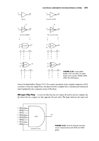
                                 0  0     0                  0  0     1     FIGURE 5.42: Logic gates:
                                 0  1     1                  0  1     0     Buffer, NOT (inverter), tri-state
                                 1  0     1                  1  0     0     buffer and inverter, NAND, NOR,
                                 1  1     0                  1  1     1     XOR, Not XOR gates.


                             form n-bit data buffers (Figure 5.47). For output operations from a digital computer to D/A
                             converter or discrete output lines, the data from the computer bus is latched and maintained
                             (until updated by the computer) using D-flip flops.


                             RS-type Flip-Flop   A reset-set flip-flop has two inputs (R and S) and two outputs (Q,
                              ̄
                             Q) where the two outputs are the opposite of each other. The logic between the input and


                             0  Bit 7
                              1  Bit 6
                              1  Bit 5
                             0  Bit 4                          out
                             0  Bit 3          AND
                              1  Bit 2
                             0  Bit 1
                              1  Bit 0
                                                                    FIGURE 5.43: An 8-bit address decoder
                                                                    circuit implemented with NOT and AND
                                           Decoder (8 bit)
                                                                    gates.
   320   321   322   323   324   325   326   327   328   329   330