Page 330 - Mechatronics with Experiments
P. 330

JWST499-Cetinkunt
            JWST499-c05
                       316   MECHATRONICS  Printer: Yet to Come                     October 28, 2014 11:15 254mm×178mm
                                                         Decoder
                                  CPU   Address
                                          bus
                                                                               5 V
                                                IN
                                        Control
                                          bus
                                         Data   DI                    Q    R
                                          bus
                                                                      Q    S
                                                                     R-S
                                                                     Flop-flop
                                                                               5 V


                                                         Decoder
                                  CPU   Address
                                          bus


                                        Control  OUT
                                          bus
                                                DO                   D    Q
                                         Data
                                          bus                                                  5 V
                                                                     E    Q  Inverting   R
                                                                            driver
                                                                  D Flop-flop      LED
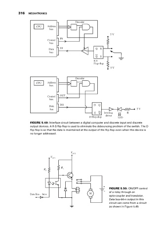
                              FIGURE 5.49: Interface circuit between a digital computer and discrete input and discrete
                              output devices. A R-S flip-flop is used to eliminate the debouncing problem of the switch. The D
                              flip-flop is so that the data is maintained at the output of the flip-flop even when this device is
                              no longer addressed.


                                                       V
                                                        CC2
                                          V CC1


                                                 R
                                      R           1
                                       2


                                                                              FIGURE 5.50: ON/OFF control
                                                                           –  of a relay through an
                              Data Bus -  bit n                   M
                                                                              opto-coupler and transistor.
                                                                              Data bus-bit-n output in this
                                                                              circuit can come from a circuit
                                                                              as shown in Figure 5.49.
   325   326   327   328   329   330   331   332   333   334   335