
Page 333 - Mechatronics with Experiments
P. 333
Printer: Yet to Come
October 28, 2014 11:15 254mm×178mm
JWST499-Cetinkunt
JWST499-c05
ELECTRONIC COMPONENTS FOR MECHATRONIC SYSTEMS 319
OUT
SELECT
Hold
Data bus DONE
START + Sample Anti- V in
Logic circuit – & aliasing
hold filter
Dn-1
Dn-2
Bus
driver
D1
D0
D/A
IN
SELECT A/D converter
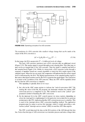
FIGURE 5.53: Operating principles of an A/D converter.
The resolution of a D/A converter (the smallest voltage change that can be made at the
output of the D/A converter) is
n
ΔV = V (R ∕R) = V range ∕2 − 1 (5.316)
f
h
n
In that range, the D/A can provide (2 − 1) different levels of voltage.
The basic A/D converter operation uses a D/A converter plus an additional circuit
(Figure 5.53). The analog signal is passed through an anti-aliasing filter. This filter may or
may not be an integral part of the A/D converter. Then the signal is sampled and held at
the sampled level (Figure 5.54). While it is being held, a D/A converter cycles through a
sequence of numbers based on a search algorithm to match the D/A output signal to the
sampled signal. When the two are equal, the comparator will indicate that the correct signal
level is determined by the D/A. The digital representation of the sampled analog signal is
the same as the digital number used by the D/A to generate the equal signal. The conversion
is accurate to the resolution of the A/D converter. Then, the CPU will be signalled about
the fact that the A/D conversion is complete.
This signaling is typically done in two ways:
1. Set a bit in the ADC status register to indicate the “end-of-conversion ADC.” By
reading the value of this bit, the program can determine whether the current ADC
conversion process is completed or not. This method is used in the “polled” (pro-
grammed) method of handling the ADC conversion.
2. Set the interrupt bit in the ADC control register (or status register, depending on
where the interrupt bit is implemented for the particular microcontroller) to generate
an interrupt to the CPU, indicating that the ADC conversion process is complete. This
is used in the interrupt driven ADC conversion handling method. The application
program must be setup to service this interrupt, which is simply providing a sub-
routine (called “interrupt service routine” (ISR)) to read the ADC data register.
The CPU would then read the data on the D/A portion of the A/D through the data
bus. Notice that this type of A/D conversion is an interative process and takes a longer time