Page 336 - Mechatronics with Experiments
P. 336

JWST499-Cetinkunt
            JWST499-c05
                       322   MECHATRONICS  Printer: Yet to Come                     October 28, 2014 11:15 254mm×178mm
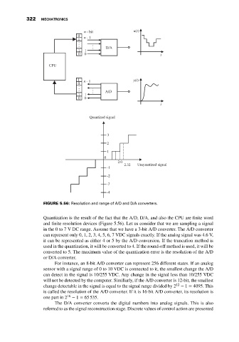
                                               n - bit              u(t)
                                            0  n - 1
                                            1
                                                        D/A
                                             1  1
                                             0  0                              t
                                CPU


                                            1  n - 1                y(t)
                                            0
                                                        A/D
                                             1  1
                                             0  0
                                                                               t


                                                 Quantized signal


                                                         3
                                                         2
                                                         1
                                                        0
                                                             2.0
                                                                2.32  Unquantized signal
                                                         -1
                                                         -2

                                                         -3
                                                         -4

                              FIGURE 5.56: Resolution and range of A/D and D/A converters.

                              Quantization is the result of the fact that the A/D, D/A, and also the CPU are finite word
                              and finite resolution devices (Figure 5.56). Let us consider that we are sampling a signal
                              in the 0 to 7 V DC range. Assume that we have a 3-bit A/D converter. The A/D converter
                              can represent only 0, 1, 2, 3, 4, 5, 6, 7 VDC signals exactly. If the analog signal was 4.6 V,
                              it can be represented as either 4 or 5 by the A/D conversion. If the truncation method is
                              used in the quantization, it will be converted to 4. If the round-off method is used, it will be
                              converted to 5. The maximum value of the quantization error is the resolution of the A/D
                              or D/A converter.
                                   For instance, an 8-bit A/D converter can represent 256 different states. If an analog
                              sensor with a signal range of 0 to 10 VDC is connected to it, the smallest change the A/D
                              can detect in the signal is 10/255 VDC. Any change in the signal less than 10/255 VDC
                              will not be detected by the computer. Similiarly, if the A/D converter is 12-bit, the smallest
                              change detectable in the signal is equal to the signal range divided by 2 12  − 1 = 4095. This
                              is called the resolution of the A/D converter. If it is 16-bit A/D converter, its resolution is
                              one part in 2 16  − 1 = 65 535.
                                   The D/A converter converts the digital numbers into analog signals. This is also
                              referred to as the signal reconstruction stage. Discrete values of control action are presented
   331   332   333   334   335   336   337   338   339   340   341