Page 328 - Mechatronics with Experiments
P. 328

JWST499-Cetinkunt
            JWST499-c05
                       314   MECHATRONICS  Printer: Yet to Come                     October 28, 2014 11:15 254mm×178mm
                              triggered either by a predefined edge transition signal of a clock or input sampled in a high
                              state of clock signal and transferred to the output at the trailing edge of the clock signal.
                              JK flip-flops are used in counters. For instance, four JK-flip flops can be used to count up
                              to sixteen.


                       5.8 DIGITAL AND ANALOG I/O AND THEIR
                             COMPUTER INTERFACE

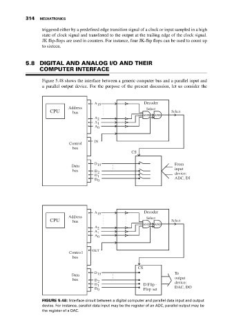
                              Figure 5.48 shows the interface between a generic computer bus and a parallel input and
                              a parallel output device. For the purpose of the present discussion, let us consider the


                                                     A 15                 Decoder
                                         Address                           Select
                                 CPU       bus                                        Select
                                                                          AND  AND
                                                     A 2
                                                     A 1
                                                     A 0


                                                     IN
                                          Control
                                           bus
                                                                     CS

                                                     D                                 From
                                           Data       15
                                           bus       D 2                               input
                                                     D 1                               device:
                                                     D 0                               ADC, DI


                                                     A 15                 Decoder
                                         Address                           Select
                                 CPU       bus                                        Select
                                                                          AND  AND
                                                     A 2
                                                     A 1
                                                     A 0


                                                    OUT
                                          Contro l
                                           bus

                                                                        CS
                                                     D 15                              To
                                           Data
                                           bus       D 2                               output
                                                     D 1                  D Flip -     device:
                                                     D 0                  Flop set     DAC, DO

                              FIGURE 5.48: Interface circuit between a digital computer and parallel data input and output
                              device. For instance, parallel data input may be the register of an ADC, parallel output may be
                              the register of a DAC.
   323   324   325   326   327   328   329   330   331   332   333