Page 326 - Mechatronics with Experiments
P. 326

JWST499-Cetinkunt
            JWST499-c05
                       312   MECHATRONICS  Printer: Yet to Come                     October 28, 2014 11:15 254mm×178mm
                                              0
                                              1
                               Input          2
                              channels                       Output
                                              3             channel
                                                Multiplexer
                                              4
                                              5
                                              6
                                              7
                                                A  B  C


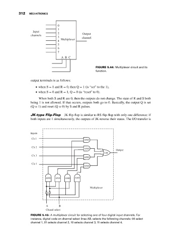
                                                                     FIGURE 5.44: Multiplexer circuit and its
                                                                     function.

                              output terminals is as follows:
                                  when S = 1 and R = 0, then Q = 1 (is “set” to the 1),

                                  when S = 0 and R = 1, Q = 0 (is “reset” to 0).

                                   When both S and R are 0, then the outputs do not change. The state of R and S both
                              being 1 is not allowed. If that occurs, outputs both go to 0. Basically, the output Q is set
                              (Q = 1) and reset (Q = 0) by S and R pulses.

                              JK-type Flip-Flop   JK flip-flop is similar to RS flip-flop with only one difference: if
                              both inputs are 1 simultaneously, the outputs of JK reverse their states. The I/O transfer is


                              Inputs
                              Ch 1
                                                              AND
                              Ch 2
                                                              AND
                                                                                 Output
                                                                          OR
                              Ch 3
                                                              AND
                              Ch 4
                                                              AND


                                       AND   AND  AND   AND


                                                                 Multiplexer


                                       A       B
                                       Chanel select
                              FIGURE 5.45: A multiplexer circuit for selecting one of four digital input channels. For
                              instance, digital code on channel select lines AB, selects the following channels: 00 select
                              channel 1, 01 selects channel 2, 10 selects channel 3, 11 selects channel 4.
   321   322   323   324   325   326   327   328   329   330   331