
Page 324 - Mechatronics with Experiments
P. 324
JWST499-Cetinkunt
JWST499-c05
310 MECHATRONICS Printer: Yet to Come October 28, 2014 11:15 254mm×178mm
A
A B
+ +
B
- -
+6 V +6 V
10 K 10 K
A A
10 K 10 K
B B
out out
A B out A out A B out
A out
AND 0 0 0 OR 0 0 0
B 0 1 0 B 0 1 1
1 0 0 1 0 1
1 1 1 1 1 1
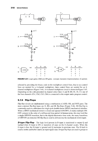
FIGURE 5.41: Logic gates: AND and OR gates - concept, transistor implementation, IC symbol.
selected by providing the binary code on the multiplexer control lines, that is two control
lines are needed for a 4-channel multiplexer, three control lines are needed for an 8-
channel multiplexer (Figure 5.44). A 4-channel multiplexer circuit is shown in Figure 5.45.
Depending on the code presented in channel select lines A and B (00, 01, 10, 11) one of
the four channels (Ch1, Ch2, Ch3, Ch4) is connected to the output under program control.
5.7.4 Flip-Flops
Flip-flop circuits are implemented using a combination of AND, OR, and NOT gates. The
most common flip-flop types are D, RS, and JK flip-flops (Figure 5.46). RS flip-flop is
commonly used as a debouncer for single-pole double-throw (SPDT) mechanical switches.
When a SPDT mechanical switch is closed and opened (ON/OFF), it makes multiple ON-
OFF contacts in the order of a millisecond time period. In human terms, this may look like
a single OFF/ON transition, but in the digital electronics time scale, the many transitions
of OFF/ON are detected. RS flip-flop is used in debouncing the mechanical switch input.
D-type Flip-Flop The logic level present in D-input is transferred to output Q and
latched when E-input is ON or transition of state on the E-channel occurs. When the
E-input is low, the D-input is ignored and Q maintains its previous state. The D-latch is
used to strobe and buffer (latch) an input signal state. D-type flip flops are used in groups to