
Page 321 - Mechatronics with Experiments
P. 321
Printer: Yet to Come
October 28, 2014 11:15 254mm×178mm
JWST499-c05
JWST499-Cetinkunt
ELECTRONIC COMPONENTS FOR MECHATRONIC SYSTEMS 307
– –
Solar
cell + +
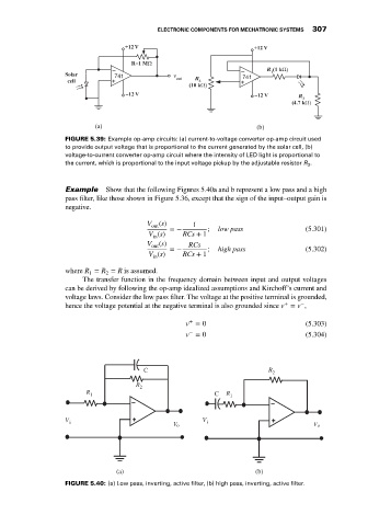
FIGURE 5.39: Example op-amp circuits: (a) current-to-voltage converter op-amp circuit used
to provide output voltage that is proportional to the current generated by the solar cell, (b)
voltage-to-current converter op-amp circuit where the intensity of LED light is proportional to
the current, which is proportional to the input voltage pickup by the adjustable resistor R 3 .
Example Show that the following Figures 5.40a and b represent a low pass and a high
pass filter, like those shown in Figure 5.36, except that the sign of the input–output gain is
negative.
V out (s) =− 1 ; low pass (5.301)
V (s) RCs + 1
in
V out (s) RCs
=− ; high pass (5.302)
V (s) RCs + 1
in
where R = R = R is assumed.
2
1
The transfer function in the frequency domain between input and output voltages
can be derived by following the op-amp idealized assumptions and Kirchoff’s current and
voltage laws. Consider the low pass filter. The voltage at the positive terminal is grounded,
+
−
hence the voltage potential at the negative terminal is also grounded since v = v ,
+
v = 0 (5.303)
−
v = 0 (5.304)
C R 2
R 2
R 1 C R 1
V i V i
V o V o
(a) (b)
FIGURE 5.40: (a) Low pass, inverting, active filter, (b) high pass, inverting, active filter.