
Page 397 - Mechatronics with Experiments
P. 397
October 9, 2014 8:1
Printer: Yet to Come
JWST499-c06
JWST499-Cetinkunt
SENSORS 383 254mm×178mm
TABLE 6.1: RTD temperature sensor
materials and the resistance–
temperature sensitivity coefficient.
Material
Aluminum 0.00429
Copper 0.0043
Gold 0.004
Platinum 0.003927
Tungsten 0.0048
◦
RTDs may be used to measure the cryogenic temperature to approximately 700 C
temperature range. Platinum is one of the most common materials used in RTD sensors. The
main advantages of RTD sensors are that the resistance–temperature relationship is fairly
linear over a wide temperature range and the measurement accuracy can be as small as
◦
±0.005 C. Furthermore, the drift of the sensor over time is very small, typically in the range
◦
of less than 0.1 C∕year. As a result, RTDs do not require frequent calibration. A RTD is a
passive device. It has a resistance where the resistance changes linearly with temperature.
One good way of converting the change in resistance to voltage is to use the RTD in a
Wheatstone bridge circuit. The dynamic response of the RTD sensor is relatively slow
compared to other temperature sensors. RTDs can not be used to measure high frequency
transient temperature variations.
Thermistor Temperature Sensors Thermistor sensors are based on semicon-
ductor materials where the resistance of the sensing element reduces exponentially with
the temperature. The typical resistance and temperature relationship for a thermistor is
approximately,
( )
β 1 − 1
R = R ⋅ e T T o (6.175)
o
where is also a function of temperature and a property of the semiconductor material.
The variation in the resistance of a thermistor for a given temperature change is much
larger than the variation in resistance of a RTD sensor. This type of sensor is used for
their high sensitivity, high bandwidth, and ruggedness compared to RTDs. However, the
manufacturing variations in thermistors can be large from one sensor to another. Therefore,
they cannot be used as direct replacements to one another. As a result, each sensor must be
properly calibrated before replacement.
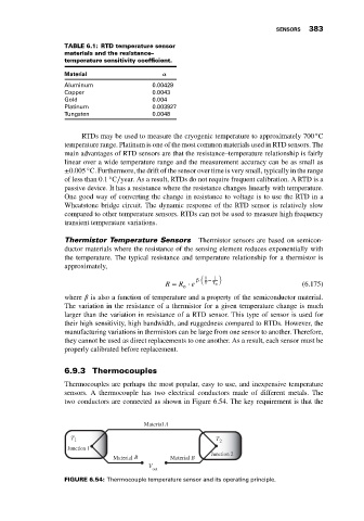
6.9.3 Thermocouples
Thermocouples are perhaps the most popular, easy to use, and inexpensive temperature
sensors. A thermocouple has two electrical conductors made of different metals. The
two conductors are connected as shown in Figure 6.54. The key requirement is that the
Material A
T 1 T 2
Junction 1
Material B Material B Junction 2
V
out
FIGURE 6.54: Thermocouple temperature sensor and its operating principle.