Page 402 - Mechatronics with Experiments
P. 402

JWST499-Cetinkunt
            JWST499-c06
                       388   MECHATRONICS  Printer: Yet to Come                       October 9, 2014 8:1  254mm×178mm
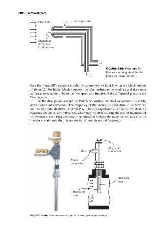
                                   Flow field            Staticpressure


                                   Stagnation
                                   point, u=2
                                   Total pressure


                                                                        P
                                                                          1
                                                                             FIGURE 6.59: Pitot tube for
                                                                             flow rate sensing via diffential
                                                                  P 2        pressure measurement.


                              Note that Bernoulli’s equation is valid for a compressible fluid flow up to a Mach number
                              of about 0.2. For higher Mach numbers, the relationship can be modified and the sensor
                              calibrated to accurately obtain the flow speed as a function of the differential pressure and
                              Mach number.
                                   As the flow passes around the Pitot tube, vortices are shed as a result of the tube
                              surface and fluid interaction. The frequency of the vortices is a function of the flow rate
                              and the pitot tube diameter. A given Pitot tube can experience a certain vortex shedding
                              frequency around a certain flow rate which may result in exciting the natural frequency of
                              the Pitot tube. Each Pitot tube sensor specification includes the range of flow rate to avoid
                              in order to make sure that it is not excited around its natural frequency.


                                                                              Stagnation
                                                             Flow             connection

                                                       Static
                                                       connection


                                                                                    Stationary
                                                                                    point


                                                        Stagnation
                                                        point


                              FIGURE 6.60: Pitot tube sensor picture and typical application.
   397   398   399   400   401   402   403   404   405   406   407