
Page 403 - Mechatronics with Experiments
P. 403
October 9, 2014 8:1
Printer: Yet to Come
JWST499-Cetinkunt
JWST499-c06
SENSORS 389 254mm×178mm
Measured
Pressure pressure Permanent pressure drop
drop caused by the sensor
P u
P
d
u d
P P
u d
Differential
pressure
sensor
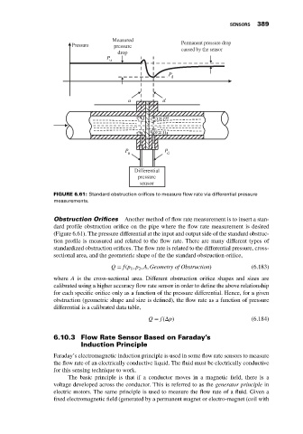
FIGURE 6.61: Standard obstruction orifices to measure flow rate via differential pressure
measurements.
Obstruction Orifices Another method of flow rate measurement is to insert a stan-
dard profile obstruction orifice on the pipe where the flow rate measurement is desired
(Figure 6.61). The pressure differential at the input and output side of the standard obstruc-
tion profile is measured and related to the flow rate. There are many different types of
standardized obstruction orifices. The flow rate is related to the differential pressure, cross-
sectional area, and the geometeric shape of the the standard obstruction orifice,
Q = f(p , p , A, Geometry of Obstruction) (6.183)
2
1
where A is the cross-sectional area. Different obstruction orifice shapes and sizes are
calibrated using a higher accuracy flow rate sensor in order to define the above relationship
for each specific orifice only as a function of the pressure differential. Hence, for a given
obstruction (geometric shape and size is defined), the flow rate as a function of pressure
differential is a calibrated data table,
Q = f(Δp) (6.184)
6.10.3 Flow Rate Sensor Based on Faraday’s
Induction Principle
Faraday’s electromagnetic induction principle is used in some flow rate sensors to measure
the flow rate of an electrically conductive liquid. The fluid must be electrically conductive
for this sensing technique to work.
The basic principle is that if a conductor moves in a magnetic field, there is a
voltage developed across the conductor. This is referred to as the generator principle in
electric motors. The same principle is used to measure the flow rate of a fluid. Given a
fixed electromagnetic field (generated by a permanent magnet or electro-magnet (coil with