
Page 399 - Mechatronics with Experiments
P. 399
October 9, 2014 8:1
Printer: Yet to Come
JWST499-Cetinkunt
JWST499-c06
SENSORS 385 254mm×178mm
6.10 FLOW RATE SENSORS
There are four main groups of sensors to measure the flow rate of a fluid (liquid or gas)
passing through a cross-sectional area:
1. mechanical flow rate sensors,
2. differential pressure measurement based flow rate sensors,
3. thermal flow rate sensors,
4. mass flow rate sensors.
6.10.1 Mechanical Flow Rate Sensors
There are three major types of mechanical flow rate sensors: positive displacement flow rate
sensors, turbine flow meters, and drag flow meters. Their operating principle is based on
the volume displaced by the fluid flow and drag between the fluid and the sensing element.
Positive Displacement Flow Meters Positive displacement flow meters work
on the same principle as the positive displacement hydraulic pumps and motors (see Chap-
ter 7). The positive displacement pumps (and motors) are so named because they displace a
well-defined fluid volume per revolution. For instance, a gear pump or piston pump sweeps
a fixed amount of volume per revolution. This is called the displacement of the pump in
units of D = Volume∕Revolution. If the rotational speed of the pump is known, w shaft , then
the amount of fluid flow rate (Q)that passes through the pump or motor is determined by
Q = D ⋅ w (6.177)
shaft
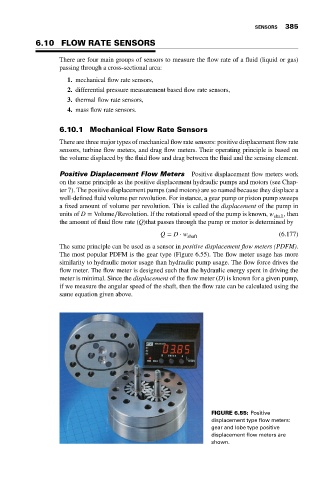
The same principle can be used as a sensor in positive displacement flow meters (PDFM).
The most popular PDFM is the gear type (Figure 6.55). The flow meter usage has more
similarity to hydraulic motor usage than hydraulic pump usage. The flow force drives the
flow meter. The flow meter is designed such that the hydraulic energy spent in driving the
meter is minimal. Since the displacement of the flow meter (D) is known for a given pump,
if we measure the angular speed of the shaft, then the flow rate can be calculated using the
same equation given above.
FIGURE 6.55: Positive
displacement type flow meters:
gear and lobe type positive
displacement flow meters are
shown.