
Page 398 - Mechatronics with Experiments
P. 398
JWST499-Cetinkunt
JWST499-c06
384 MECHATRONICS Printer: Yet to Come October 9, 2014 8:1 254mm×178mm
connections between the two conductors at both ends must form a good electrical con-
nection. The fundamental thermoelectric phenomenon is that there is a voltage differential
developed between the open circuit end of the conductor proportional to the temperature of
the one of the junctions relative to the temperature of the other junction. The thermoelectric
phenomena is a result of the flow of both heat and electricity over a conductor. This is called
the Seebeck effect, named after Thomas J. Seebeck who first observed this phenomenon in
1821. The voltage differential measured at the output of the thermocouple is approximately
proportional to the temperature differential between the two points (V out in Figure 6.54),
V out ≈ K ⋅ (T − T ) (6.176)
2
1
Notice that the proportionality constant is a function of the thermocouple materials. The
thermocouple materials refer to the material types used for conductors A and B. Further-
more, it is not exactly constant, but varies with temperature by a small amount.
The proportionality constant is a very good approximation for many types of ther-
mocouples over large temperature ranges. This makes the thermocouples very attractive
sensors due to their linearity over large temperature ranges. The voltage output of the
thermocouple is in the milli Volt (mV) range and must be amplified by an op-amp circuit
before it is used by a data acquisition system.
A thermocouple measures the temperature difference between its two junctions. In
order to measure the temperature of one of the junctions, the temperature of the other
junction must be known. Therefore, a reference temperature is required for the operation
of the thermocouple. This reference can be provided by either ice-water or by a built-in
electronic reference temperature. The measurement error in most thermocouples is around
◦
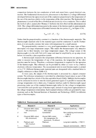
±1to2 C. Different thermocouple material pairs are designated with a standard letter to
simplify references to them (Table 6.2).
In most cases, the output of the thermocouple is processed by a digital computer
system. The reference temperature is provided by a thermistor based sensor as part of the
thermocouple interface circuit of the data aquisition board (DAQ). Multiple thermocouples
can be connected in series to sum the sensor generated signal or in parallel to measure the
average temperature over a finite area. Computer interface cards for thermocouple signal
processing make use of the standard thermocouple tables for the voltage to temperature
conversion for each specific type of thermocouple, instead of using linear approximation to
the voltage–temperature relationship. Such standard reference tables are generated by orga-
nizations such as the National Institute of Standards and Technology (NIST) for different
types of thermocouples.
TABLE 6.2: Thermocouple types and their applications.
Type Material A Material B Applications
◦
E Chromel (90% nickel, Constantan (55% copper, Highest sensitivity, < 1000 C
10% chromium) 45% nickel)
J Iron Constantan Non-oxidizing environment,
◦
< 700 C
◦
K Chromel (90% nickel, Alumel (94% nickel, < 1400 C
10% chromium) 3% manganese, 2%
aluminum, 1% silicon)
◦
S Platinum and Platinum Long term stability, < 1700 C
10% rhodium
◦
T Copper Constantan Vacuum environment, < 400 C