
Page 400 - Mechatronics with Experiments
P. 400
JWST499-Cetinkunt
JWST499-c06
386 MECHATRONICS Printer: Yet to Come October 9, 2014 8:1 254mm×178mm
Magnetic
pickup
Support Support
retainer retainer
S.S. body Rotor
Flow
direction
Rear Bearing Shaft bushing Front
rotor Flush rotor
support Hole Trast ball support
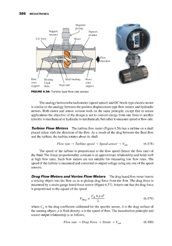
FIGURE 6.56: Turbine type flow rate sensor.
The analogy between the tachometer (speed sensor) and DC brush-type electric motor
is similar to the analogy between the positive displacement type flow meters and hydraulic
motors. Both motor and sensor version work on the same principle, except that in sensor
applications the objective of the design is not to convert energy from one from to another
(electric to mechanical or hydraulic to mechanical), but rather to measure speed or flow rate.
Turbine Flow Meters The turbine flow meter (Figure 6.56) has a turbine on a shaft
placed inline with the direction of the flow. As a result of the drag between the fluid flow
and the turbine, the turbine rotates about its shaft.
Flow rate → Turbine speed → Speed sensor → V out (6.178)
The speed of the turbine is proportional to the flow speed (hence the flow rate) of
the fluid. The linear proportionality constant is an approximate relationship and holds well
at high flow rates. Such flow meters are not suitable for measuring low flow rates. The
speed of the turbine is measured and converted to output voltage using any one of the speed
sensors.
Drag Flow Meters and Vortex Flow Meters The drag based flow meter inserts
a sensing object into the flow so as to pickup drag force from the flow. The drag force is
measured by a strain-gauge based force sensor (Figure 6.57). It turns out that the drag force
is proportional to the square of the speed.
C A u 2
d
F drag = (6.179)
2
where C is the drag coefficient calibrated for the specific sensor, A is the drag surface of
d
the sensing object, is fluid density, u is the speed of flow. The transduction principle and
sensor output relationship is as follows,
Flow rate → Drag Force → Strain → V out (6.180)