
Page 404 - Mechatronics with Experiments
P. 404
JWST499-Cetinkunt
JWST499-c06
390 MECHATRONICS Printer: Yet to Come October 9, 2014 8:1 254mm×178mm
Magnets
Conductive fluid
flow direction
Induced voltage
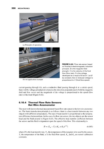
(a) Principle of operation
Sensor inline with flow pipe
FIGURE 6.62: Flow rate sensor based
on Faraday’s electromagnetic induction
principle. B is the magnetic field
strength, V is the velocity of the fluid
flow (flow rate), E is the voltage
developed as a result of B and V.Let B
be constant, then E (induced voltage) is
(b) An application example proportional to V (fluid flow speed).
current passing through it)), and a conductive fluid passing through it at a certain speed,
there will be voltage potential developed in the direction perpendicular to both the magnetic
field and flow vector and the magnitude of the voltage is proportional to the speed (flow
rate) of the fluid (Figure 6.62).
6.10.4 Thermal Flow Rate Sensors:
Hot Wire Anemometer
The most well-known thermal measurement based flow rate sensor is the hot wire anemome-
ter. The basic transduction principle is as follows: there is a heat transfer between any two
objects with different temperatures. The rate of heat transfer is proportional to the tempera-
ture difference between them. In the case of a flow rate sensor, the two objects are the sensor
head and the fluid around it (Figure 6.63). The effective heat transfer coefficient between
the sensor and the fluid is dependent upon the speed of the flow. This relationship is
̇ H = (T − T )(K + K u 1∕2 ) (6.185)
w f o 1
where ̇ H is the heat transfer rate, T the temperature of the tungsten wire used by the sensor,
w
T the temperature of the fluid, u is the fluid flow speed, K and K are sensor calibration
o
f
1
constants.