
Page 408 - Mechatronics with Experiments
P. 408
JWST499-Cetinkunt
JWST499-c06
394 MECHATRONICS Printer: Yet to Come October 9, 2014 8:1 254mm×178mm
6.12 VISION SYSTEMS
Vision systems, also called computer vision or machine vision, are general purpose sensors.
They are called the “smart sensors” in industry since what is sensed by a vision system
totally depends on the image processing software. A typical sensor is used to measure a
variable, that is temperature, pressure, length, and so on. A vision system can be used to
measure shape, orientation, area, defects, differences between parts, and so forth. Vision
technology has improved significantly over the past 20 years, to the extent that they are
rather standard “smart sensing components” in most factory automation systems for part
inspection and location detection. Their lower cost makes them increasingly attractive
for use in automated processes. Furthermore, vision systems are now standard in mobile
equipment safety systems to detect obstacles and avoid collisions, especially when used
with radar based obstacle detection systems.
There are three main components of a vision system (Figures 6.67, 6.68),
1. vision camera: this is the sensor head, made of a photosensitive device array such as
charge coupled device (CCD) and optical lens,
2. image processing computer hardware (converts the CCD voltage to digital data) and
software to process the image,
3. lighting system.
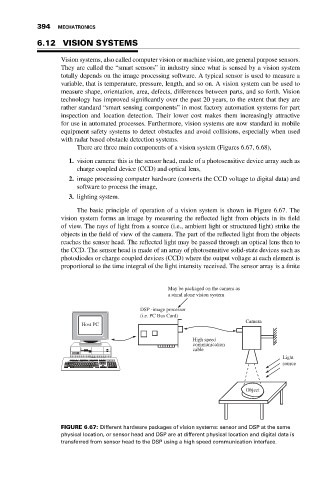
The basic principle of operation of a vision system is shown in Figure 6.67. The
vision system forms an image by measuring the reflected light from objects in its field
of view. The rays of light from a source (i.e., ambient light or structured light) strike the
objects in the field of view of the camera. The part of the reflected light from the objects
reaches the sensor head. The reflected light may be passed through an optical lens then to
the CCD. The sensor head is made of an array of photosensitive solid-state devices such as
photodiodes or charge coupled devices (CCD) where the output voltage at each element is
proportional to the time integral of the light intensity received. The sensor array is a finite
May be packaged on the camera as
a stand alone vision system
DSP -image processor
(i.e. PC Bus Card)
Camera
Host PC
High speed
communication
cable
Light
source
Object
FIGURE 6.67: Different hardware packages of vision systems: sensor and DSP at the same
physical location, or sensor head and DSP are at different physical location and digital data is
transferred from sensor head to the DSP using a high speed communication interface.