
Page 401 - Mechatronics with Experiments
P. 401
Printer: Yet to Come
October 9, 2014 8:1
JWST499-c06
JWST499-Cetinkunt
SENSORS 387 254mm×178mm
Supporting flexible
beam Strain gauges
Drag
element
FIGURE 6.57: Strain-gauge based
drag measurement type flow rate
sensor.
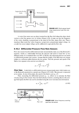
A vortex flow meter uses an object inserted into the flow field where the object sheds
vortices as the flow passes over its surface (Figure 6.58). It turns out that the frequency
of the vortex shedding is proportional to the speed of the flow, hence flow rate. Then a
transducer that counts the vortex frequency can provide a proportional output voltage. As
a result, the sensor output voltage can be calibrated to represent the flow rate.
6.10.2 Differential Pressure Flow Rate Sensors
Flow rate sensors based on differential pressure measurements make use of the Bernoulli’s
equation, which is a relationship between the pressure and speed of fluid flow at two
different points. It is estimated that over 50% of all flow rate measuring devices are based
on differential pressure type sensors. Assume that the height of the fluid does not change
relative to a reference plane between the two points. Then the pressure and speed of the
fluid at two separate cross-sections are related by
u 2 u 2
p + 1 = p + 2 (6.181)
1 2
2 2
Pitot Tube A pitot tube is a differential pressure measurement sensor which makes use
of the Bernoulli equation for a special case (Figures 6.59, 6.60). The pressure is measured
at two points. At one of the points, the speed of the fluid is zero u = 0.
2
Then, measuring the differential pressure p − p allows us to calculate the fluid
2 1
velocity along its flow stream. Once the fluid velocity is known, assuming that it is the aver-
age fluid speed, the flow rate can be calculated using the cross-sectional area information.
2 1∕2
u = (p − p ) (6.182)
1
1
2
Flow
Drag Vortex FIGURE 6.58: Vortex frequency counting
element Pipe wall type flow rate sensor.