
Page 184 - Servo Motors and Industrial Control Theory -
P. 184
180 Appendix A
53. In problem 52, the two tanks were not interconnected and the derivation of the
governing differential equations were simpler. The diagram below shows two
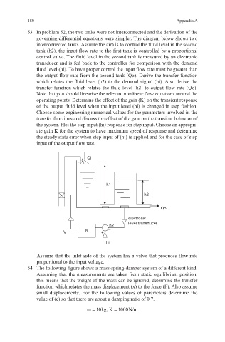
interconnected tanks. Assume the aim is to control the fluid level in the second
tank (h2), the input flow rate to the first tank is controlled by a proportional
control valve. The fluid level in the second tank is measured by an electronic
transducer and is fed back to the controller for comparison with the demand
fluid level (hi). To have proper control the input flow rate must be greater than
the output flow rate from the second tank (Qo). Derive the transfer function
which relates the fluid level (h2) to the demand signal (hi). Also derive the
transfer function which relates the fluid level (h2) to output flow rate (Qo).
Note that you should linearize the relevant nonlinear flow equations around the
operating points. Determine the effect of the gain (K) on the transient response
of the output fluid level when the input level (hi) is changed in step fashion.
Choose some engineering numerical values for the parameters involved in the
transfer functions and discuss the effect of the gain on the transient behavior of
the system. Plot the step input (hi) response for step input. Choose an appropri-
ate gain K for the system to have maximum speed of response and determine
the steady state error when step input of (hi) is applied and for the case of step
input of the output flow rate.
Qi
h1
h2
Qo
electronic
level transducer
h2
V K + –
hi
Assume that the inlet side of the system has a valve that produces flow rate
proportional to the input voltage.
54. The following figure shows a mass-spring-damper system of a different kind.
Assuming that the measurements are taken from static equilibrium position,
this means that the weight of the mass can be ignored, determine the transfer
function which relates the mass displacement (x) to the force (F). Also assume
small displacements. For the following values of parameters determine the
value of (c) so that there are about a damping ratio of 0.7.
m10kg, K= = 1000N/m