
Page 182 - Servo Motors and Industrial Control Theory -
P. 182
178 Appendix A
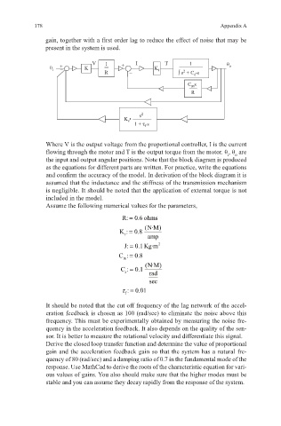
gain, together with a first order lag to reduce the effect of noise that may be
present in the system is used.
V 1 I T 1 θ
θ i + – – K R + – K t ∫ s + C •s o
2
c
C s
m
R
s 2
K •
s
1 + τ s
f
Where V is the output voltage from the proportional controller, I is the current
flowing through the motor and T is the output torque from the motor. θ , θ are
o
i
the input and output angular positions. Note that the block diagram is produced
as the equations for different parts are written. For practice, write the equations
and confirm the accuracy of the model. In derivation of the block diagram it is
assumed that the inductance and the stiffness of the transmission mechanism
is negligible. It should be noted that the application of external torque is not
included in the model.
Assume the following numerical values for the parameters,
R: 0.6 ohms=
(N·M)
K : 0.8=
t
amp
=
J: 0.1 Kg·m 2
=
C : 0.8
m
(N·M)
=
C : 0.1
s rad
sec
τ =
: 0.01
f
It should be noted that the cut off frequency of the lag network of the accel-
eration feedback is chosen as 100 (rad/sec) to eliminate the noise above this
frequency. This must be experimentally obtained by measuring the noise fre-
quency in the acceleration feedback. It also depends on the quality of the sen-
sor. It is better to measure the rotational velocity and differentiate this signal.
Derive the closed loop transfer function and determine the value of proportional
gain and the acceleration feedback gain so that the system has a natural fre-
quency of 80 (rad/sec) and a damping ratio of 0.7 in the fundamental mode of the
response. Use MathCad to derive the roots of the characteristic equation for vari-
ous values of gains. You also should make sure that the higher modes must be
stable and you can assume they decay rapidly from the response of the system.