
Page 181 - Servo Motors and Industrial Control Theory -
P. 181
Appendix A 177
R
Vi Vo
C
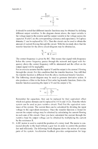
It should be noted that different transfer functions may be obtained by defining
different output variables. In the diagram shown above, the input variable is
the voltage input to the resistor and the output variable is the voltage across the
capacitor. R and C are the corresponding resistance and capacitance. In Laplace
domain, C can be replaced by 1/Cs. Then the circuit can be used to obtain the
amount of current flowing through the circuit. With this in mind, show that the
transfer function for the above circuit diagram may be obtained as,
V o := 1
V R Cs 1⋅ ⋅+
i
The corner frequency is given by RC. This means that signal with frequency
below the corner frequency passes through the network and signal with fre-
quency above the corner frequency will be attenuated and the effect on the
output signal will be negligible.
For an exercise assume that the input is Vi and the output is the current I flowing
through the circuit. For this condition find the transfer function. You will find
the transfer function is different from the above mentioned transfer function.
50. The following circuit diagram may be used to generate derivative action. It
also produces a filter in the form of first order lag transfer function. Derive the
transfer function assuming the input is Vi and the output is Vo.
C1
Vo
Vi R
C2
Remember for capacitors, they can be replaced by their equivalent effect
which in Laplace domain can be replaced by 1/C1s and 1/C2s. Then the whole
system can be used as pure resistive circuit. Find first the equivalent resis-
tance of the system. The current then can be calculated by dividing the input
voltage to the equivalent resistance. Once the transfer function is found for
current the output voltage may be obtained by calculating the current flowing
in each arm of the circuit. Once you have calculated the current through the
resistive load the output voltage can be obtained by multiplying the current
by the resistance R.
51. A DC motor is used to control the position of a rotary load. The motor is con-
nected directly to the load without a gear box in order to control the position
fast and efficiently. The following block diagram shows the action of various
parts of the system. Acceleration feedback provides compensation for large