
Page 183 - Servo Motors and Industrial Control Theory -
P. 183
Appendix A 179
You may find difficulties to improve the damping of the system. In this case,
add a velocity feedback with gain of K . The velocity must be obtained from the
v
output position and fed back to the proportional controller. In practice, a small
DC motor known as tachometer is attached to the motor and the signal is fed
back to the controller. Now with three parameters of the gain of proportional,
derivative, and acceleration you should be able to locate the roots in proper
position in the s plane.
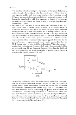
52. In process industry it is often required to control the level of fluid in tanks. The
figure below shows a two tank system. In reality it is required to control the
level of the fluid in both tanks which means that this system is two inputs and
two output variables problem. This problem will be investigated in the next sec-
tion where multivariable control systems are studied. At this stage assume that
only the level of fluid in the second tank must be controlled. With this in mind
derive the transfer function of the system. Note that you should linearize the
relevant nonlinear flow equation around an operating point. Remember that the
problem becomes two inputs and single output variable problem. First draw the
block diagram when you write the differential equations. Using principle super-
position find the two transfer functions which relates the output variable h2 to
the command signal (hi) and the transfer function which relates the fluid level
(h2) to the output flow rate which is controlled by a variable valve. Assume a
proportional controller with gain K is used
Q1
h1
Q2
Electric
valve V K h2 Qo
hi
Level
Sensor
Select some engineering values for the parameters involved in the transfer
function. To have proper control the flow rate from the main valve should be
greater than the output flow from the first tank and also the input flow rate to
the second tank should be greater than the output flow rate. The output flow
rate from the second valve is controlled by the operator. Remember that the
output from the first tank is only proportional to fluid level as the output flow
rate from the second tank is determined by the user. Having substituted nu-
merical values for the parameters, discuss the effect of gain K on the transient
behavior of the system and steady state values for single step input of the output
flow rate and step input of demand signal (hi).