
Page 47 - GuardII+ Series 4208 Platform EV User Manual
P. 47
User Instructions
• At this time, different signals can be linked together; this will cause the Total
Displacement Summary Number to be analyzed as a vector quantity of the linked
inputs in addition to each individual axis being analyzed separately.
NOTE:
Only signals that are produced by sensors that have the same install
location and are monitoring a different axis can be linked.
For example, a radial and tangential axis from 2 sensors mounted on the
phase lead at slot #42 can be linked. If they were both radial signals, or if
one sensor was on the ring bus at slot #15, then they could not be linked.
• Additionally, the sensor signal can be inverted for IAM’s Operational Deflection Shape
(or ODS) animation if a particular sensor is physically installed in the opposite
orientation than the others.
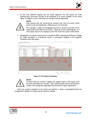
Figure 6-13 EV Signal Orientation
NOTE:
A sensor that can monitor 2 signals will appear twice on this page; once
for each axis that it can monitor. Each signal that the sensor can produce
needs to be configured regarding that axis that the signal represents.
Once the sensors installed on the Asset are defined, a report is generated listing the
configuration details; this report can be saved or printed.
41
www.irispower.com