
Page 24 - GuardII+ Series 4208 Platform Flux User Manual
P. 24
Installation
• Signal and communications cables shall run along grounded metal surfaces like metal
conduits, metal trunking or ducts, preferably away from power cables. They should
not run on open trays alongside power cables.
• The conduits shall be installed with insulated fixings as required to ensure grounding
only at one end. For conduit sizes follow the local electric codes.
• Shielded cables should have the shield grounded only at one end of cable segments
to avoid circulating currents through the shield.
5.2. Sensor Termination Boxes
Flux probes for a GuardII+ require a separate sensor termination box. Refer to the
appropriate Installation Guides for instructions to install the probes and termination box.
5.3. Mounting Location
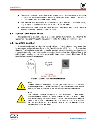
Excessive cable lengths distort Flux signals, although Flux signals are more tolerant than
in some other technologies available in the GuardII+ Series 4208 Platform. The standard
GuardII+ Flux installation kit includes cables for connecting the monitor to the termination box;
the total distance from the flux probe to the monitor should be less than 150 m (500’). If the
cable lengths required appear to be unavoidably long, please contact Iris Power LP for
consultation or possible alternatives.
Figure 5-1 GuardII+ Flux Installation Location
Note:
Different GuardII+ monitoring technologies have different installation
location requirements. When deciding on the installation location for the
monitor, be sure to consider all the installed monitoring technologies.
Note:
The maximum distance represents a best-case scenario. Flux signal
integrity depends on multiple factors; the probe used, the type of cable
used, cable routing and specific site conditions. The distance from the flux
probe to the GuardII+ monitor should be as small as possible to achieve
the best signal quality. Any excess cable should be trimmed to the
minimum length and not coiled.
18
www.irispower.com